Automatic rack equipment of textile embroidery machine

An embroidery machine and frame technology, which is applied in the field of embroidery machines, can solve the problems of staff burden, limited range of movement of the embroidery machine head, and reduced work efficiency, and achieve the effects of good stability, continuous embroidery, and high precision

Inactive Publication Date: 2021-03-23
周建明
View PDF0 Cites 4 Cited by
  • Summary
  • Abstract
  • Description
  • Claims
  • Application Information

AI Technical Summary

Problems solved by technology

[0003] However, when the existing computerized embroidery machines are embroidering long patterns, due to the limited range of movement of the embroidery machine head, it is necessary to manually adjust the position of the embroidery cloth to make it embroider continuously, which brings a greater burden to the staff and cannot Effectively ensure the continuous work of the subsequent embroidery cloth. At the same time, during the embroidery process, it is necessary to maintain an effective distance between the embroidery cloth and the machine head. However, the machine head itself does not have the adjustment function, and the traditional cloth stand cannot be adjusted, resulting in a greatly reduced working efficiency.

Method used


Image

  • Automatic rack equipment of textile embroidery machine
  • Automatic rack equipment of textile embroidery machine
  • Automatic rack equipment of textile embroidery machine

Examples


Embodiment Construction

[0034]The present invention will be described in detail below in conjunction with the appended drawings, and the technical solutions in the embodiments of the present invention will be clearly and completely described. Obviously, the described embodiments are only some of the embodiments of the present invention, not all of them. Based on the embodiments of the present invention, all other embodiments obtained by persons of ordinary skill in the art without making creative efforts all belong to the protection scope of the present invention; in addition, the terms "first", "second", "Third", "Up, Down, Left, Right", etc. are used for descriptive purposes only and are not to be construed as indicating or implying relative importance. At the same time, in the description of the present invention, unless otherwise clearly stipulated and limited, the terms "connected" and "connected" should be understood in a broad sense, for example, it can be a fixed connection, a detachable conne...


PUM


Abstract

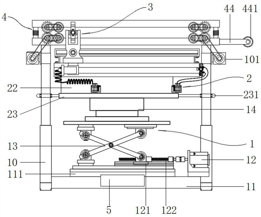
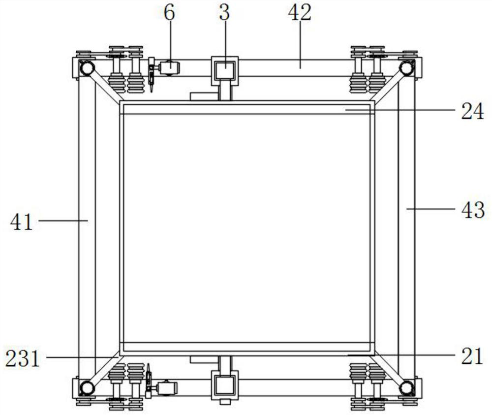
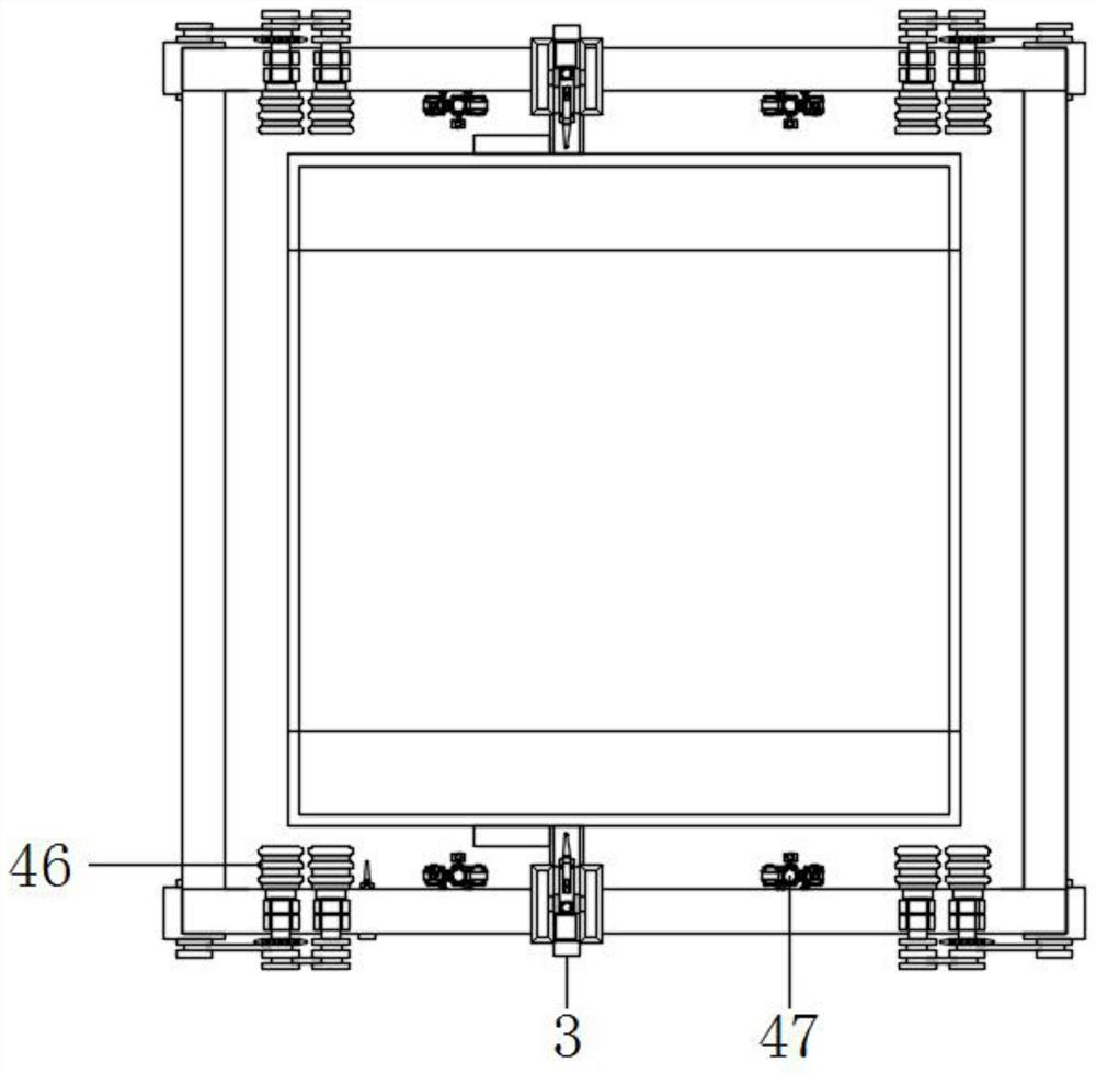
The invention discloses automatic rack equipment of a textile embroidery machine, and relates to the technical field of embroidery machines. The automatic rack equipment comprises a lifting device, the lifting device is mainly composed of hydraulic support rods, a base, a motor B, a shear fork frame and an I-shaped table, the hydraulic support rods are vertically mounted at four corners of the base, a sliding table is arranged in the center of the top of the base, the motor B is mounted on one side of the sliding table, the shear fork frame is mounted at the top of the sliding table, one footof the shear fork frame is fixedly connected to the position, close to the front end, of the surface of the sliding table, the bottom of the other foot of the shear fork frame is connected with a sliding block A, the bottom of the sliding block A is in relative sliding connection with the sliding table, and a screw rod is arranged in the sliding block A in a penetrating mode. The position of embroidery cloth can be automatically adjusted, so that the embroidery cloth is effectively matched with a machine head to continuously carry out long-pattern embroidery, manual adjustment is not needed, the burden of workers is reduced, meanwhile, the distance between embroidery cloth and the machine head can be effectively adjusted, embroidery precision and work efficiency are improved, and pattern errors are reduced.

Description

technical field [0001] The invention relates to the technical field of embroidery machines, in particular to an automatic rack equipment for textile embroidery machines. Background technique [0002] The invention of the computer embroidery machine is an important guarantee to promote the advancement of the textile industry and the garment industry. The computer embroidery machine first uses the embroidery CAD software to make plates, and after generating the samples, put the disks containing the embroidery programs and patterns into the computer disk drives. In the process, under the control of the program, the computer changes the pattern coordinates into electrical signals equivalent to the displacement in the X and Y directions of the stretching frame, and sends them to the X, Y, and Z single-chip microcomputer systems for motor speed-up and down processing, and outputs three-phase six-beat No., the power amplifier box of the thread motor performs power amplification, an...

Claims


Application Information

Patent Timeline
Patent Type & Authority Applications(China)
IPC IPC(8): D05C9/22D05C9/20
CPCD05C9/20D05C9/22
Inventor 金诚
Owner 周建明
Why Eureka
Try Eureka