
Distributed parameterized impeller self-circulation treatment casing

A technology for handling casing and self-circulation, applied in mechanical equipment, non-variable-capacity pumps, non-displacement pumps, etc., can solve the problem that the structural parameters of the air bleed channel and the bridge path are not optimized, the impeller efficiency is negative, Simple structure and other problems, to achieve the effect of expanding stable working range, reducing efficiency loss and improving stall margin

Active Publication Date: 2021-03-23
NORTHWESTERN POLYTECHNICAL UNIV
View PDF3 Cites 2 Cited by
  • Summary
  • Abstract
  • Description
  • Claims
  • Application Information

AI Technical Summary

Problems solved by technology

Common self-circulation casings for centrifugal impellers mainly have two defects. First, the traditional centrifugal impeller self-circulation treatment casings usually cover 100% of the circumference, and the amount of bleed air under different flow conditions is relatively large. In this case the efficiency of the impeller will have a large negative effect
Second, the structure of the traditional centrifugal impeller self-circulation treatment casing is simple, and the structural parameters such as the bleed air channel and the bridge profile have not been optimized, and there is still a large room for improvement in its stable working margin

Method used


Image

  • Distributed parameterized impeller self-circulation treatment casing
  • Distributed parameterized impeller self-circulation treatment casing
  • Distributed parameterized impeller self-circulation treatment casing

Examples


Embodiment Construction

[0020] This embodiment is a distributed parameterized impeller self-circulation processing casing.

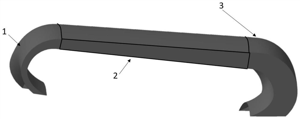
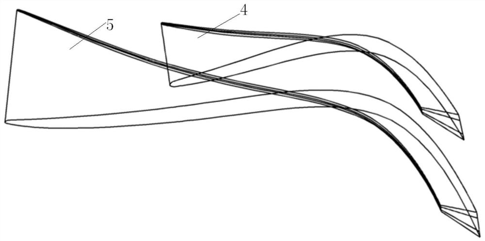
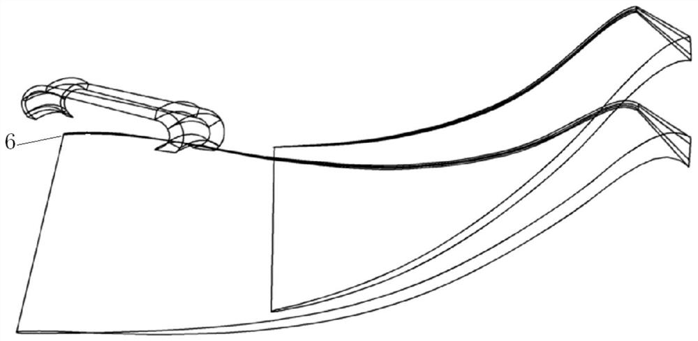
[0021] refer to Figure 1 ~ Figure 3 , the distributed parameterized impeller self-circulation processing casing in this embodiment is composed of impeller casing, channel leading edge 6, impeller blades, front channel 1, rear channel 2 and bleed air bridge 3; wherein, bleed air bridge The road is fixed on the outside of the impeller casing, by connecting the front channel 1 and the rear channel 2 of the front edge 6 of the upper channel of the impeller casing, the gas backflow in the bridge circuit is realized by using the pressure difference between the front and rear of the centrifugal impeller channel.

[0022] In this embodiment, there are multiple bleed bridges 3, and the two impeller passages correspond to a bleed bridge of a self-circulating casing. The circumferential coverage angle of each bleed bridge 3 is 22.5°; the inner wall surface is two-dimensional The profile...


PUM


Abstract

The invention discloses a distributed parameterized impeller self-circulation treatment casing which is composed of a casing body, an air inlet channel, impeller blades, a front channel, a rear channel and air entraining bridge circuits; the air entraining bridge circuits are fixed to the outer side of an impeller casing, and air flows back in the bridge circuits through the front channel and therear channel connected to a channel front edge of the impeller casing; and the front channel and the rear channel of the impeller self-circulation treatment casing are located at the positions with different axial chord lengths away from an impeller inlet respectively, an inner wall face two-dimensional molded line is formed by fitting and optimizing a structured curve so as to ensure that jet flow is close to the wall face as much as possible, and the outer wall face molded line is a controllable contraction molded line, so that the effects of guiding and accelerating airflow are achieved. The impeller self-circulation treatment casing utilizes the airflow pressure difference in rotor channels corresponding to the self-circulation front channel and the self-circulation rear channel to perform air exhaust and air injection. According to the treatment casing structure, the blocking margin and the stall margin of the centrifugal impeller can be improved, the purpose of reducing the efficiency loss is achieved, and the impeller can operate and work at a larger margin.

Description

technical field [0001] The invention relates to the technical field of impellers, in particular to a distributed parameterized impeller self-circulation processing casing, which is used to improve the stability margin of a centrifugal impeller and reduce efficiency loss. Background technique [0002] In the prior art, the centrifugal impeller, as a general machine for increasing gas pressure, has been widely used in many sectors of the national economy, especially in the field of aviation. Aeroengines pursue higher thrust-to-weight ratio and higher reliability. Centrifugal impellers, as an important part of the compressor in aeroengines, are also developing towards high efficiency, high pressure ratio, and high reliability. [0003] In order to expand the stability margin of the centrifugal impeller and increase its efficiency and pressure ratio under small flow conditions, researchers have developed a variety of control methods. As a passive control method, casing processi...

Claims


Application Information

Patent Timeline
Patent Type & Authority Applications(China)
IPC IPC(8): F04D17/10F04D29/54F04D29/28F04D29/30F04D29/66
CPCF04D17/10F04D29/541F04D29/284F04D29/30F04D29/667F05D2220/3216
Inventor 吴艳辉张紫云王振洋
Owner NORTHWESTERN POLYTECHNICAL UNIV
Learn More