Pipe circumferential pure shearing loading method and device

A loading device, pure shearing technology, applied in the direction of measuring device, testing material strength by applying stable shear force, analyzing materials, etc.

Pending Publication Date: 2021-03-23
HARBIN INST OF TECH +1
View PDF1 Cites 2 Cited by
  • Summary
  • Abstract
  • Description
  • Claims
  • Application Information

AI Technical Summary

Problems solved by technology

[0008] The purpose of the present invention is to provide a method and device for hoop pure shear loading of pipes, so as to solve the above-mentioned problems in the prior art, so that the pipe to be tested is always in a stable hoop pure shear loading state during the torsional deformation process

Method used


Image

  • Pipe circumferential pure shearing loading method and device
  • Pipe circumferential pure shearing loading method and device
  • Pipe circumferential pure shearing loading method and device

Examples


Embodiment 1

[0040] This embodiment provides a hoop pure shear loading method for pipes, such as Figure 1-8 shown, including:

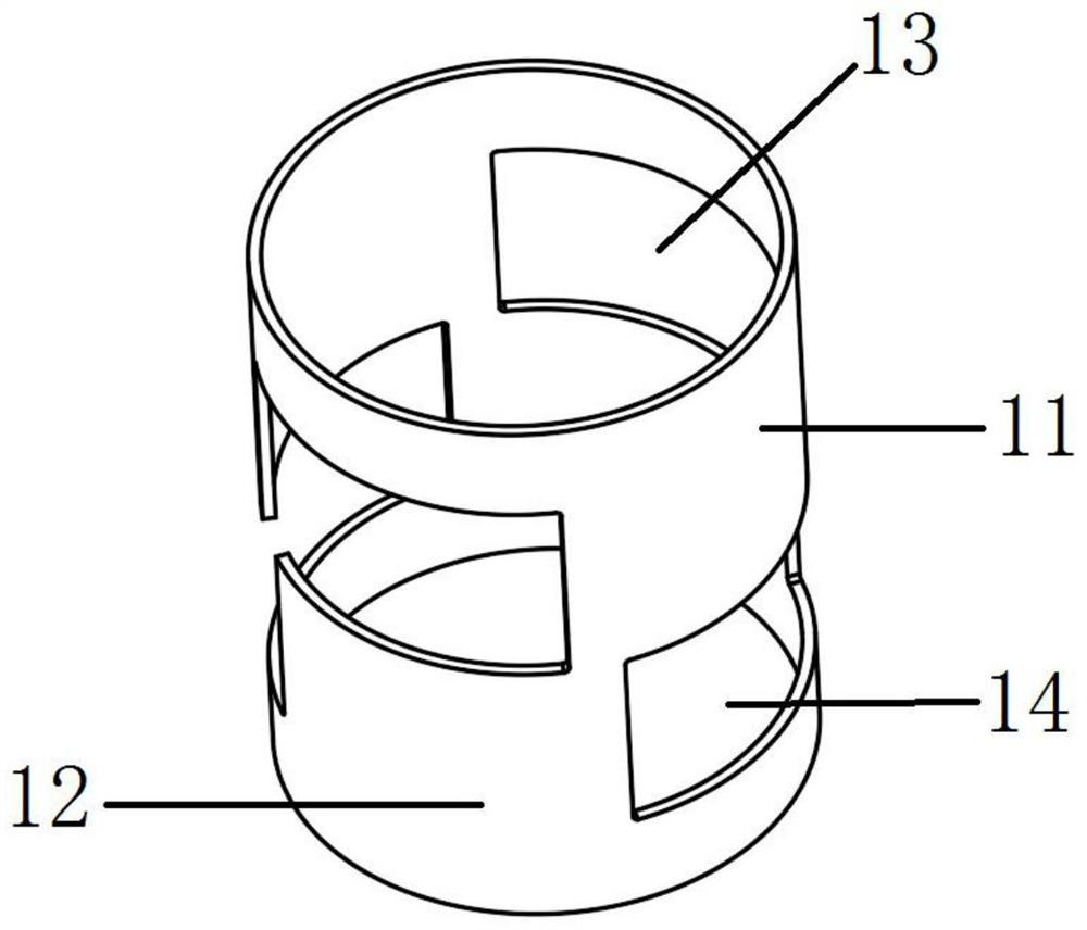
[0041] Step 1: Divide the pipe 9 to be detected axially into an upper pipe 11 and a lower pipe 12 through a circumferential dividing line located on the side wall of the pipe 9 to be tested. The plane where the circumferential dividing line is located is perpendicular to the axis of the pipe. On the side wall of the pipe material 9 to be detected, a first gap 13 extending upward to the pipe material 11 is provided from the ring to the boundary line, and a second gap 14 extending downward to the pipe material 12 is provided on the side wall of the pipe material 9 to be detected from the ring to the boundary line, and makes The upper pipe material 11 and the lower pipe material 12 form a state connected only by the connecting portion, such as figure 2 For the pipe style shown in , the number of connection parts can be one or more;

[0042] Step 2: Insert the man...

Embodiment 2

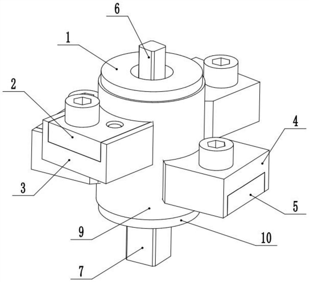
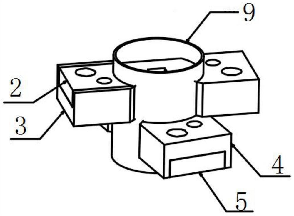
[0046] This embodiment provides a device for realizing the pipe hoop pure shear loading method described in Embodiment 1, such as Figure 1-8 As shown, it includes: a twisting device and a mandrel, the mandrel is used to be inserted in the pipe to be detected 9 along the axial direction of the pipe, the shearing surface 17 in the twisting device can be against the first edge and the second edge and can The first edge and the second edge respectively apply opposite and circumferential torsion forces along the pipe; the torsion device is also provided with several anti-deformation surfaces, and each anti-deformation surface is used to abut against the first notch 13 and the second notch respectively 14 On the remaining edges except the first edge and the second edge, each anti-deformation surface is respectively used to resist the deformation of each edge, therefore, the device provided in this embodiment can be used to realize the method in the first embodiment.

[0047] Furthe...


PUM


Abstract

The invention provides a pipe circumferential pure shearing loading method and device, and relates to the technical field of pipe mechanical property testing. According to the technical scheme, the method includes the steps that a notch is machined in a to-be-detected pipe in advance, a connecting part is reserved, and a core shaft is arranged to prevent the side wall of the pipe from being twisted and deformed inwards in a twisting process; and then opposite torsional force in the circumferential direction of the pipe is applied to the first edge and the second edge through a torsion device,the upper pipe is twisted relative to the lower pipe, a plurality of anti-deformation surfaces are further arranged on the torsion device, and each anti-deformation surface is respectively propped against the other edges, except the first edge and the second edge, of the first notch and the second notch so as to prevent the other edges from deforming when the upper pipe and the lower pipe are twisted. According to the invention, the pipe circumferential pure shearing loading method and device provided by the invention can enable the to-be-detected pipe to be always in a stable circumferentialpure shearing loading state in the torsional deformation process when the to-be-detected pipe is subjected to torsional shearing.

Description

technical field [0001] The invention relates to the technical field of pipe mechanical performance testing, in particular to a pipe hoop pure shear loading method and device. Background technique [0002] Pipes are widely used in the production of the national economy. The cross-sectional shapes are round, square and special-shaped. The most commonly used pipes are round cross-sections. In addition to being directly used as load-bearing components, tubular parts after plastic processing are often used as structural parts. Typical forming methods include high-pressure forming of pipes and bending of pipes. Representative parts include automobile body chassis structures, various aircraft and Curved axis piping in automobiles, etc. [0003] In order to avoid failure phenomena such as wrinkling and cracking in the plastic forming process of the pipe, it is necessary to understand the mechanical properties of the pipe used, use the results of computer numerical simulation to rea...

Claims


Application Information

Patent Timeline
Patent Type & Authority Applications(China)
IPC IPC(8): G01N3/24G01N3/22
CPCG01N3/22G01N3/24G01N2203/0021G01N2203/0025G01N2203/0075G01N2203/0274G01N2203/0641
Inventor 王小松胡卫龙刘钢苑世剑
Owner HARBIN INST OF TECH
Why Eureka
Try Eureka