
Electricity meter mounting rack

A technology for mounting racks and electric meters, which is applied in the direction of measuring devices, measuring electric variables, instruments, etc., can solve the problems of easy damage to the meter body, weak anti-vibration performance of mechanical electric meters, and affecting indication accuracy, so as to ensure safety, facilitate meter reading and Maintenance and life-enhancing effects

Active Publication Date: 2021-03-23
PINGYIN POWER SUPPLY CO OF STATE GRID SHANDONG ELECTRIC POWER CO +1
View PDF9 Cites 5 Cited by
  • Summary
  • Abstract
  • Description
  • Claims
  • Application Information

AI Technical Summary

Problems solved by technology

[0002] The mechanical indicating ammeter is an electrical instrument that uses electromagnetic force to make the movable part of the measuring mechanism produce mechanical actions to reflect the measured size; the electrical quantity that the mechanical indicating ammeter can accept is current, voltage or the product of two currents, etc.; because the measuring mechanism can The nature and size of the directly received electricity are limited, so it is often necessary to use the measurement circuit to pre-convert the measured value into a transitional quantity acceptable to the measurement institution; the mechanical ammeter has weak anti-vibration performance. When the mechanical ammeter is installed on the fuselage or When placed on an object with large vibration, the watch body is also subject to large vibrations, and the watch body is easily damaged, which affects the indication accuracy

Method used


Image

  • Electricity meter mounting rack
  • Electricity meter mounting rack
  • Electricity meter mounting rack

Examples


Embodiment Construction

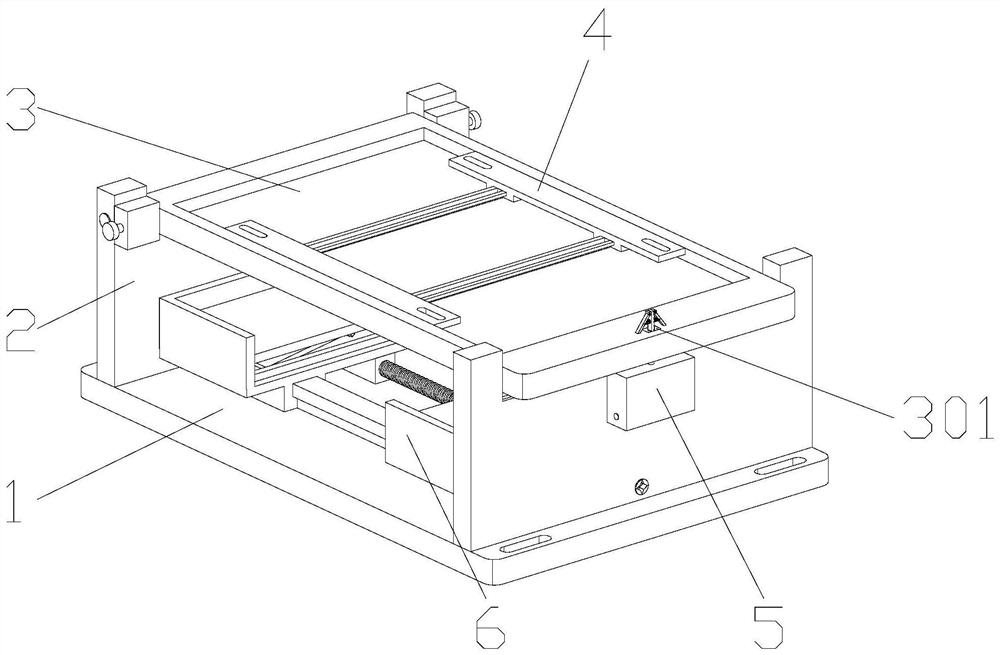
[0036] Attached below Figure 1-9 , clearly and completely describe the technical solutions in the embodiments of the present invention, obviously, the described embodiments are only some of the embodiments of the present invention, not all of them. Based on the embodiments of the present invention, all other embodiments obtained by persons of ordinary skill in the art without making creative efforts belong to the protection scope of the present invention.

[0037] In describing the present invention, it should be understood that the terms "longitudinal", "transverse", "upper", "lower", "front", "rear", "left", "right", "vertical", The orientations or positional relationships indicated by "horizontal", "top", "bottom", "inner", "outer", etc. are based on the orientations or positional relationships shown in the drawings, and are only for the convenience of describing the present invention, rather than indicating or It should not be construed as limiting the invention by imply...


PUM


Abstract

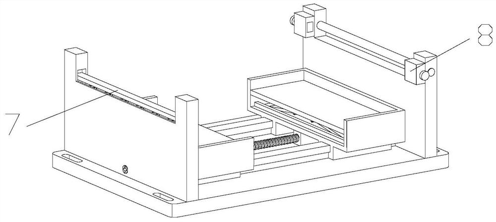
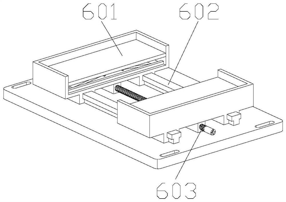
The invention discloses an electricity meter mounting rack. The electricity meter mounting rack comprises a bottom plate, two vertical plates and a supporting mechanism are mounted on the bottom plate, the two vertical plates are symmetrically mounted at the two ends of the supporting mechanism, a supporting plate and a limiting mechanism are mounted on one vertical plate, a supporting frame is mounted on the supporting plate, the limiting mechanism is matched with the supporting plate, a vibration reduction mechanism and a locking mechanism are installed on the other vertical plate, the vibration reduction mechanism is matched with the supporting plate, and the locking mechanism is installed on one side of the other vertical plate and matched with the supporting plate. More electricity meters can be installed in a limited space, workers can manage the electricity meters conveniently, more space is saved, later meter reading and maintenance of the workers are facilitated, the device has a vibration reduction function, the electricity meters can be prevented from being damaged on objects with large vibration, the indication precision of the electricity meters is guaranteed, and theservice lives of the electricity meters are prolonged.

Description

technical field [0001] The invention belongs to the technical field of electric meter installation, in particular to an electric meter installation frame. Background technique [0002] The mechanical indicating ammeter is an electrical instrument that uses electromagnetic force to make the movable part of the measuring mechanism produce mechanical actions to reflect the measured size; the electrical quantity that the mechanical indicating ammeter can accept is current, voltage or the product of two currents, etc.; because the measuring mechanism can The nature and size of the directly received electricity are limited, so it is often necessary to use the measurement circuit to pre-convert the measured value into a transitional quantity acceptable to the measurement institution; the mechanical ammeter has weak anti-vibration performance. When the mechanical ammeter is installed on the fuselage or When it is placed on an object with a large vibration, the watch body is also sub...

Claims


Application Information

Patent Timeline
IPC IPC(8): G01R11/04
CPCG01R11/04
Inventor 邱茂光侯磊房斌李俊孙绪健贾冬雪
Owner PINGYIN POWER SUPPLY CO OF STATE GRID SHANDONG ELECTRIC POWER CO
Learn More