Radar and angle adjusting device

An angle adjustment device and radar technology, applied in the optical field, can solve problems such as poor stability and reliability, difference in light transmission ratio, and large divergence angle of the peripheral field of view

Pending Publication Date: 2021-03-23
BENEWAKE BEIJING TECH CO LTD
View PDF6 Cites 0 Cited by
  • Summary
  • Abstract
  • Description
  • Claims
  • Application Information

AI Technical Summary

Problems solved by technology

[0004] There are two traditional ways to expand the field of view. The first one is to expand the field of view by rotating the prism, that is, the initial beam is reflected to each field of view through a constantly rotating reflective prism. This method can achieve a 120° field of view. Field angle scanning, but the drive circuit required by the prism is large, and the macroscopic rotation of the prism device leads to poor system stability and reliability; the second method uses ordinary objective lenses and fisheye lenses to achieve a magnification limit of 150-160° However, the change of scanning magnifica

Method used


Image

  • Radar and angle adjusting device
  • Radar and angle adjusting device
  • Radar and angle adjusting device

Examples


Embodiment Construction

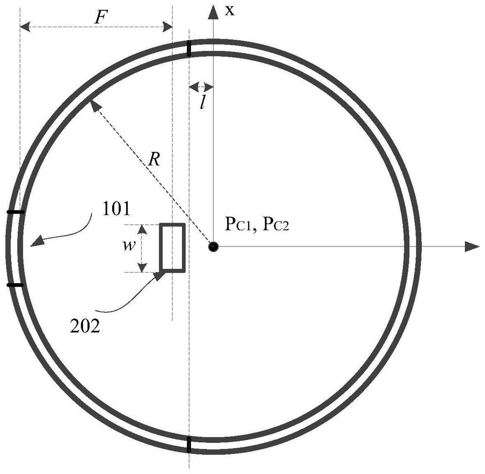
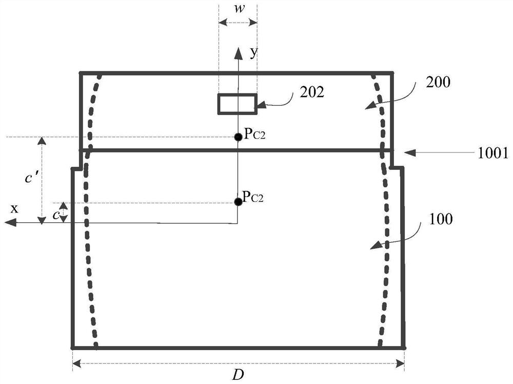
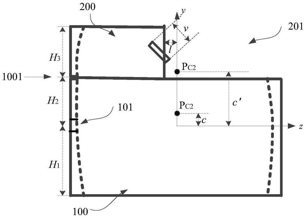
[0047] In order to make the above objects, features and advantages of the present invention more comprehensible, specific implementations of the present invention will be described in detail below in conjunction with the accompanying drawings.

[0048] In the following description, a lot of specific details are set forth in order to fully understand the present invention, but the present invention can also be implemented in other ways different from those described here, and those skilled in the art can do it without departing from the meaning of the present invention. By analogy, the present invention is therefore not limited to the specific examples disclosed below.

[0049] Secondly, the present invention is described in detail in combination with schematic diagrams. When describing the embodiments of the present invention in detail, for the convenience of explanation, the cross-sectional view showing the device structure will not be partially enlarged according to the gener...


PUM


Abstract

The invention provides a radar and an angle adjusting device. The angle adjusting device comprises a first annular spherical mirror and a second annular spherical mirror which are stacked in sequence;the curvature radiuses of the first annular spherical mirror and the second annular spherical mirror are the same; the inner surfaces of the first annular spherical mirror and the second annular spherical mirror are spherical surfaces; an initial light beam can enter a cavity of the first annular spherical mirror through a light through hole in the side wall of the first annular spherical mirror,is reflected once on the inner surface of the second annular spherical mirror after being reflected for N-1 times on the inner surface of the first annular spherical mirror, then is reflected once ona reflector in the cavity of the second annular spherical mirror after being reflected for N-2 times on the outer surface of the second annular spherical mirror, and is emitted from an outlet of thefirst annular spherical mirror or the second annular spherical mirror. According to the geometrical optics principle, the field angle range of the emitted initial light beam is larger than that of theincident initial light beam, so that the field angle range can be expanded; and when the angle adjusting device is applied to a radar, the field angle range of the radar can be expanded.

Description

technical field [0001] The invention relates to the field of optics, in particular to a radar and an angle adjustment device. Background technique [0002] Radar is a device used for distance measurement. Specifically, the initial signal emitted by the radar is reflected by the object to form an echo signal, and the echo signal is compared with the initial signal to obtain accurate information on the distance between the measured object and the radar. Among them, the initial signal can be a laser signal. The laser has the advantages of small beam divergence, concentrated energy, good directivity, and high repetition frequency, so that the laser radar can realize long-distance and high-precision measurement of the measured object. At present, lidar is widely used in aerospace, remote sensing detection, measurement, and intelligent driving. [0003] Typically, radars have a limited field of view. Traditional radar can use Micro-Electro-Mechanical System (MEMS) scanning to ex...

Claims


Application Information

Patent Timeline
IPC IPC(8): G01S7/481G01S17/08
CPCG01S7/4817G01S17/08
Inventor 杨铮郑凯李远
Owner BENEWAKE BEIJING TECH CO LTD
Why Eureka
Try Eureka