
Mode suppression resonant cavity

A mode suppression, resonant cavity technology, applied in resonators, electrical components, circuits, etc., can solve the problems of weak stray mode suppression, TE mode recognition interference, affecting test results, etc., to improve the ability to resist stray mode interference, suppress The formation of interference mode to prevent the effect of affecting the test

Pending Publication Date: 2021-03-23
METROLOGY & MEASUREMENT CENT OF CHINA ACADEMY OF ENG PHYSICS
View PDF0 Cites 0 Cited by
  • Summary
  • Abstract
  • Description
  • Claims
  • Application Information

AI Technical Summary

Problems solved by technology

However, due to the weak ability of the closed cavity structure to suppress heterogeneous modes, there is heterogeneous mode interference during the test, which interferes with the recognition of the TE mode used in the test and seriously affects the test results.

Method used


Image

  • Mode suppression resonant cavity
  • Mode suppression resonant cavity
  • Mode suppression resonant cavity

Examples


Embodiment 1

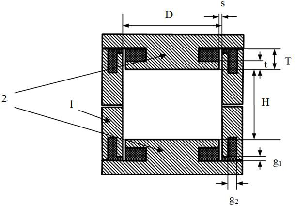
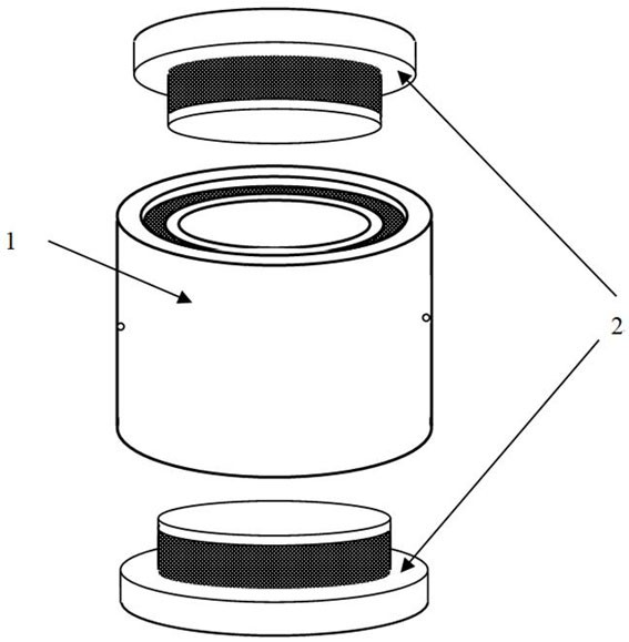
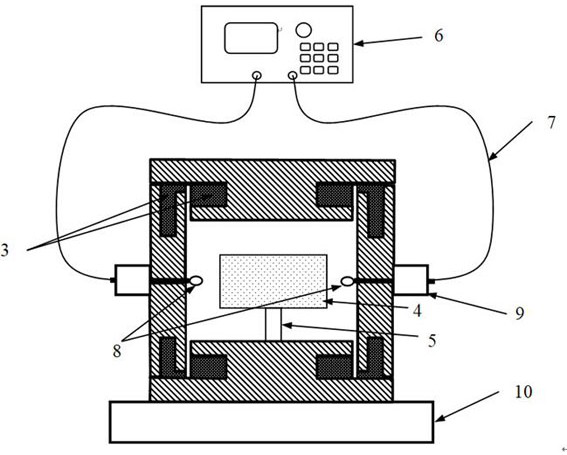
[0075] figure 1 A schematic structural diagram of a mode-suppressing resonant cavity according to an embodiment of the present invention is shown. figure 2 A schematic structural diagram of a mode-suppressing resonant cavity according to yet another embodiment of the present invention is shown. image 3 A schematic structural diagram of a mode-suppressing resonant cavity according to yet another embodiment of the present invention is shown. Figure 4 a and Figure 4 b shows a schematic structural diagram of the working state of the mode suppressing resonator according to yet another embodiment of the present invention.

[0076] like Figure 1 to Figure 4 As shown in b, the mode-suppressing resonator consists of:

[0077] Cylinder body 1, cover plate 2 and wave absorbing member 3 which are provided at both ends of the cylinder body 1;

[0078] Wherein, a resonant cavity is formed between the two cover plates 2 and the cylinder;

[0079] Wherein, the middle part of the co...


PUM


Abstract

The invention provides a mode suppression resonant cavity. The mode suppression resonant cavity comprises a cylinder, cover plates covering the two ends of the cylinder and a wave absorbing piece, wherein a resonant cavity is formed between the two cover plates and the cylinder body; the middle part of the cover plate is provided with a cover plate groove so as to enable the cross section of the cover plate along the height direction to be I-shaped, and the wave absorbing piece is filled in the cover plate groove. The mode suppression resonant cavity is high in stray mode interference resistance.

Description

technical field [0001] The invention belongs to the technical field of microwave testing, and more specifically relates to a mode suppression resonant cavity. Background technique [0002] Microwave dielectric materials are widely used in aerospace, military equipment, electronic communication and other fields, and complex permittivity is the most important electrical parameter of dielectric materials, to achieve accurate measurement of complex permittivity, for various new dielectric materials The development and practical application are of great significance. High-accuracy microwave dielectric material complex permittivity testing is generally achieved by resonant cavity methods, such as dielectric resonator method, high-Q cavity method, perturbation cavity method, quasi-optical cavity method, etc. The main principle is through coupling lines, coupling The microwave resonant cavity is excited by means such as holes, so that the resonant cavity produces electromagnetic re...

Claims


Application Information

Patent Timeline
Patent Type & Authority Applications(China)
IPC IPC(8): H01P7/06
CPCH01P7/06
Inventor 王益张翠翠王建忠于明媚郭晓东张睿
Owner METROLOGY & MEASUREMENT CENT OF CHINA ACADEMY OF ENG PHYSICS
Learn More