Antenna device and electronic equipment

An antenna device and electronic equipment technology, which is applied in directions such as antennas, antenna couplings, and antenna arrays, and can solve the problems of uncorrectable angle of arrival detection errors and large misjudgments.

Active Publication Date: 2021-03-23
GUANGDONG OPPO MOBILE TELECOMM CORP LTD
View PDF12 Cites 3 Cited by
  • Summary
  • Abstract
  • Description
  • Claims
  • Application Information

AI Technical Summary

Problems solved by technology

[0003] However, this scheme of correcting the angle of arrival according to the environmental loading conditions needs to pre-store the phase difference curves under various loading environments, so as to identify the loading environment accor

Method used


Image

  • Antenna device and electronic equipment
  • Antenna device and electronic equipment
  • Antenna device and electronic equipment

Examples


Embodiment Construction

[0029] In order to understand the characteristics and technical contents of the embodiments of the present application in more detail, the implementation of the embodiments of the present application will be described in detail below in conjunction with the accompanying drawings. The attached drawings are only for reference and description, and are not intended to limit the embodiments of the present application.

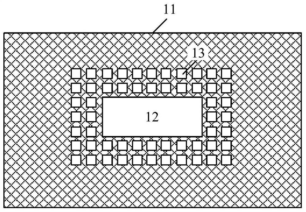
[0030] An embodiment of the present application provides an antenna device, figure 1 It is a schematic diagram of the first component structure of the antenna device in the embodiment of the present application, as shown in figure 1 As shown, the antenna device includes: a non-metallic dielectric plate 11, an antenna 12 and a plurality of electromagnetic bandgap units 13;

[0031] The antenna 12 and the plurality of electromagnetic bandgap units 13 are arranged on the non-metallic dielectric plate 11, and the plurality of electromagnetic bandgap units 13 are arrange...


PUM


Abstract

The embodiment of the invention discloses an antenna device and electronic equipment. The antenna device comprises a non-metal dielectric plate, an antenna and a plurality of electromagnetic band gapunits, wherein the antenna and the plurality of electromagnetic band gap units are arranged on the non-metal dielectric plate, and the plurality of electromagnetic band gap units are arranged around the antenna according to a first array mode; and the electromagnetic band gap units are used for suppressing surface electromagnetic wave transmission of the non-metal dielectric plate. Therefore, by arranging the electromagnetic band gap unit array around the antenna, for all incoming wave directions and antenna polarization directions, the electromagnetic band gap unit array can inhibit surface electromagnetic wave transmission of the non-metal dielectric plate and eliminate interference of surface electromagnetic waves of the non-metal dielectric plate on the antenna, so that detection of anarrival angle is irrelevant to antenna polarization, then the detection error caused by different antenna polarizations is eliminated, and the detection precision of the arrival angle is improved.

Description

technical field [0001] The present application relates to communication technology, and in particular to an antenna device and electronic equipment. Background technique [0002] Existing positioning technologies generally identify the direction of arrival of electromagnetic waves, that is, the angle of arrival, based on the phase difference of received signals between antennas. However, since the environmental loading conditions will affect the detection accuracy of the angle of arrival, it is necessary to correct the angle of arrival according to the current environmental loading conditions. Thus, the detection accuracy of the angle of arrival is ensured. [0003] However, this scheme of correcting the angle of arrival according to the environmental loading conditions needs to pre-store the phase difference curves under various loading environments, so as to identify the loading environment according to the phase difference, but this method has a large misjudgment, and can...

Claims


Application Information

Patent Timeline
IPC IPC(8): H01Q21/06H01Q1/52
CPCH01Q21/064H01Q1/52
Inventor 李偲
Owner GUANGDONG OPPO MOBILE TELECOMM CORP LTD
Why Eureka
Try Eureka