Eureka AIR delivers breakthrough ideas for toughest innovation challenges, trusted by R&D personnel around the world.

Obstacle-passing sleeve structure for drainage pipeline

A technology for drainage pipes and obstacles, which is applied in sewer pipe systems, waterway systems, pipes/pipe joints/fittings, etc. It can solve the problems of pipe support and fixation, easy to be corroded, inconvenient operation, etc., to achieve convenient installation and connection, Ensure the reliability of the connection and avoid the slippage of the casing

Pending Publication Date: 2021-03-26
WUHU XINXING DUCTILE IRON PIPES
View PDF0 Cites 0 Cited by
  • Summary
  • Abstract
  • Description
  • Claims
  • Application Information

AI Technical Summary

Problems solved by technology

However, the existing technology has the following disadvantages: the obstacles reserve holes for pipe installation. When the drainage pipe is installed, the reserved holes cannot firmly support and fix the pipe on the wall, and the risk of casing slippage is prone to occur, reducing the pipe network. Safe and reliable operation; at the same time, this type of installation method is inconvenient to operate and difficult to construct; the pre-embedded steel wall pipe has poor corrosion resistance due to the material of the pipe, and is easily corroded by the surrounding humid environment. The toughness is poor, the force or support is not firm and easy to damage, and there are hidden dangers of pipeline damage, leakage and leakage
The prefabricated concrete module inspection well is installed through the holes and pipes reserved in the well chamber. The sealing performance of the interface connection is poor, and the resistance to acid, alkali and ionic corrosion of sewage is poor.
At the same time, the rigid connection has poor resistance to foundation settlement, and the interface is easily damaged. There are hidden dangers of sewage leakage and leakage during the operation of the pipeline network, which seriously affects the performance of pipeline layout.

Method used


Image

  • Obstacle-passing sleeve structure for drainage pipeline
  • Obstacle-passing sleeve structure for drainage pipeline
  • Obstacle-passing sleeve structure for drainage pipeline

Examples


Embodiment Construction

[0024] Below with reference to the accompanying drawings, through the description of the embodiments, the specific embodiments of the present invention, such as the shape, structure, mutual position and connection relationship between the various parts, the role and working principle of the various parts, etc., will be further described. Detailed instructions:

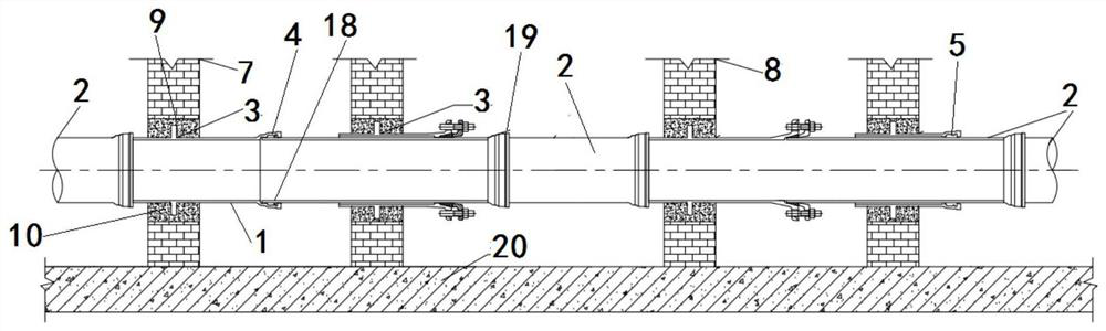
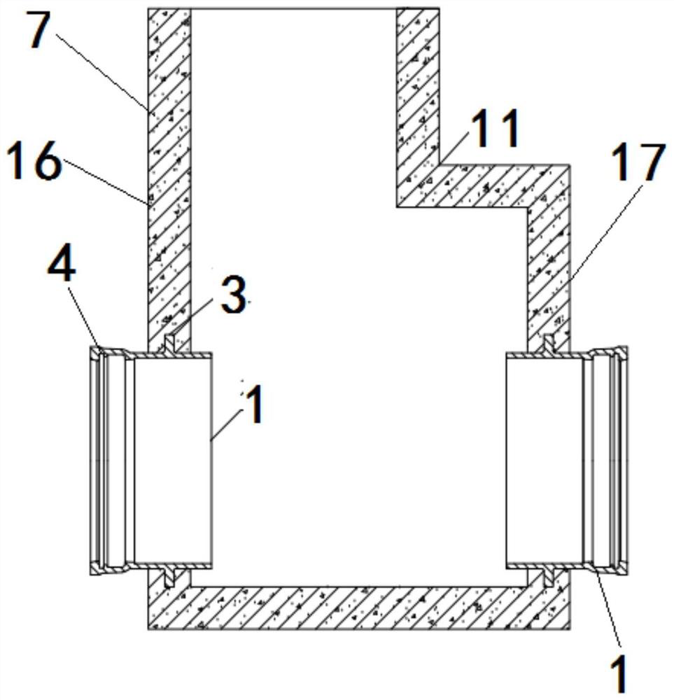
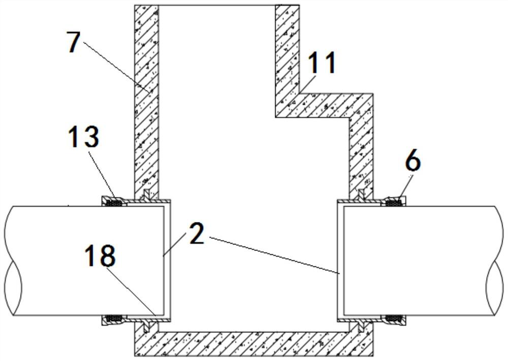
[0025] as attached figure 1 - attached Figure 5 As shown, the present invention is a casing structure for drainage pipes that passes through obstacles. The casing structure for drainage pipes that passes through obstacles includes a casing body 1 and a pipe body 2. The casing body 1 is made of metal The structure made of material, the outer surface of the sleeve body 1 is provided with a pre-embedded flange 3 arranged along the outer surface of the sleeve body 1, the end of the sleeve body 1 is provided with a bell-shaped interface 4, and the inner surface of the interface 4 is provided There are multiple grooves 5 ...


PUM


Abstract

The invention provides an obstacle-passing sleeve structure for a drainage pipeline, and belongs to the technical field of urban municipal drainage systems. A pre-embedded flange (3) is arranged on the outer surface of a sleeve body (1) of the obstacle-passing sleeve structure for the drainage pipeline, a groove part (5) is arranged on the inner surface of an interface part (4), a pipeline body (2) passes through the sleeve body (1), a silicon seal (6) is arranged in the groove part (5), the sleeve body (1) passes through an obstacle (7), and the pre-embedded flange (3) of the pipeline body (2) is pre-embedded into the obstacle (7). According to obstacle-passing sleeve structure for the drainage pipeline, the sleeve and the pipeline are convenient to construct and pre-embed, the workload is reduced, the problem that the sleeve slips off is avoided, requirements of pipeline installation reliability and practical performance are guaranteed, pipeline connection sealing performance is effectively guaranteed, seepage and leakage risks at the joint of pipeline connectors are avoided, safety performance of the drainage pipeline in use is improved, and the service life of the drainage pipeline is prolonged.

Description

technical field [0001] The invention belongs to the technical field of urban municipal drainage systems, and more specifically relates to a casing structure for drainage pipes passing through obstacles. Background technique [0002] In the current drainage industry, in the construction of drainage pipe network, such as urban municipal underground pipe network construction, culvert pipe network construction, cross-obstacle or wall pipe network construction, prefabricated concrete module inspection wells, etc. The usual practice is to reserve holes for pipeline installation or pre-embed steel wall-through pipes on obstacles to facilitate subsequent pipeline installation. At the same time, precast concrete module inspection wells are usually reserved with holes for pipe installation. However, the existing technology has the following disadvantages: the obstacles reserve holes for pipe installation. When the drainage pipe is installed, the reserved holes cannot firmly support a...

Claims


Application Information

Patent Timeline
Patent Type & Authority Applications(China)
IPC IPC(8): E03F3/04E03F3/02E03F3/06F16L5/00F16L5/10
CPCE03F3/02E03F3/04E03F3/06F16L5/00F16L5/10
Inventor 陈建华王强刘安强陈永峰
Owner WUHU XINXING DUCTILE IRON PIPES
Why Eureka
Eureka Blog
Learn More