
Six-degree-of-freedom spatial coordinate position and attitude measurement device

A technology of spatial coordinates and measuring devices, which is applied in the direction of measuring devices, measuring instruments, and optical devices, etc., can solve the problem of the quality of the return light beam or the polarization state, the requirements of the equipment site are relatively large, and the distance measurement error of the laser tracker system is extremely affected Large and other problems, to avoid beam pointing drift, ensure the accuracy of attitude measurement, and ensure the effect of vertical orthogonality

Inactive Publication Date: 2021-03-26
CHOTEST TECH INC
View PDF0 Cites 13 Cited by
  • Summary
  • Abstract
  • Description
  • Claims
  • Application Information

AI Technical Summary

Problems solved by technology

[0006] 1. The existing method uses space photogrammetry to measure the three-dimensional coordinates of the space, which requires a lot of equipment and site, and the measurement accuracy is low, and the three-axis attitude of the target cannot be measured
[0007] 2. The existing method uses a separate combination of a laser tracker and a camera for six-degree-of-freedom measurement, which has limitations in the field of view, difficulty in aligning the coordinate system, low precision in coordinate conversion, and poor engineering practicability.
[0008] 3. The existing method uses a hollow form of the retroreflector for attitude measurement, which will lead to a decrease in the performance of the retroreflector, and will have a greater impact on the quality of the returned light beam or the polarization state, which will affect the ranging error of the laser tracker system great influence

Method used


Image

  • Six-degree-of-freedom spatial coordinate position and attitude measurement device
  • Six-degree-of-freedom spatial coordinate position and attitude measurement device
  • Six-degree-of-freedom spatial coordinate position and attitude measurement device

Examples


Embodiment Construction

[0062] The present invention will be further described below with reference to the accompanying drawings and specific embodiments.

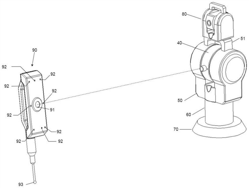
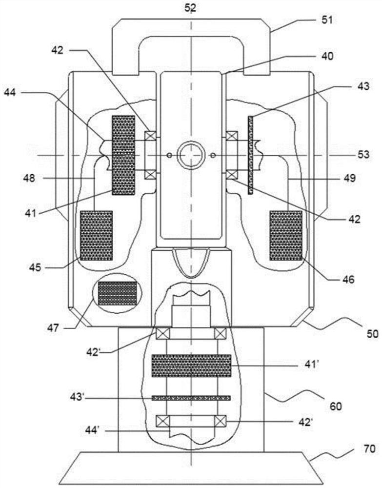
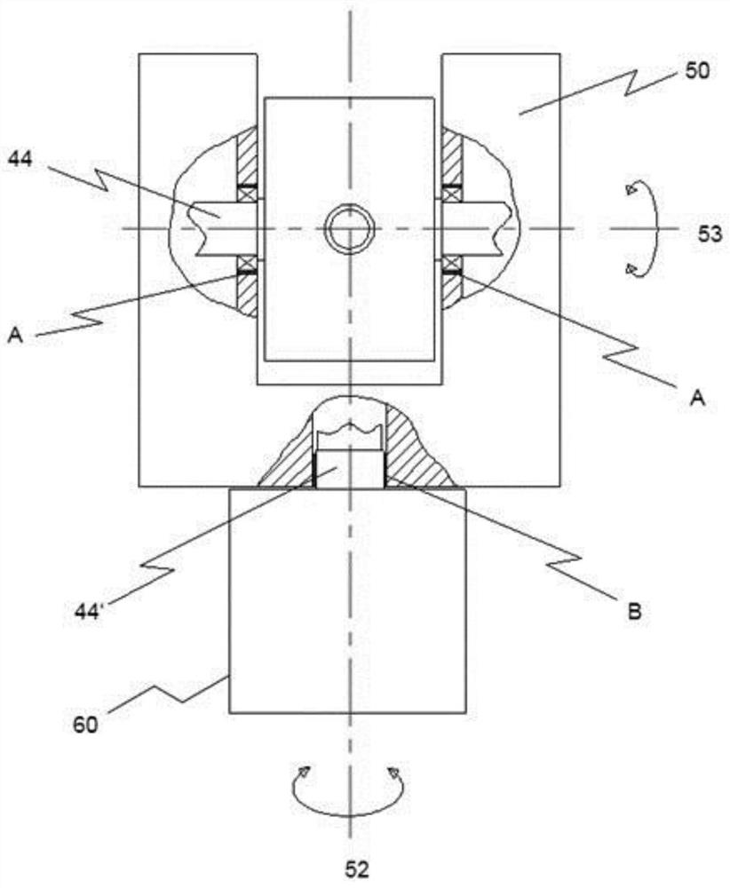
[0063] figure 1 An embodiment of a six-degree-of-freedom coordinate measuring device based on a laser tracker provided by the present invention is shown. The shown laser tracker includes a horizontal angle tracking measurement unit 60, which can be fixed on a support base device 70 (optionally a heavy-duty tripod, a light-duty tripod, and a portable fixed base, etc.). The shown laser tracker also includes a pitch angle tracking measurement unit 50 with a top bracket 51 and an optical aiming unit 40 . The gesture recognition unit 80 is fixedly attached to the top bracket 51 of the laser tracker. The optical attitude target 90 includes a retroreflector 91 , a plurality of LEDs 92 and a probe 93 . The retroreflector is used to reflect the laser beam emitted by the laser tracker, and cooperate with the laser tracker to complete the three-dimension...


PUM


Abstract

The invention provides a six-degree-of-freedom spatial coordinate position and attitude measurement device. The six-degree-of-freedom spatial coordinate position and attitude measurement device comprises a laser tracker, an attitude recognition unit and an optical attitude target, wherein the laser tracker is used for quickly tracking a target which moves in the space and is provided with the optical attitude target, aligning the target with a backward reflector on the optical attitude target, obtaining the distance from the laser tracker to the target through a retroreflection light beam, andobtaining azimuth angle and pitch angle information according to the angle measuring device at the same time; and thus, the three-dimensional position coordinates of the target are obtained. The invention has the beneficial effects that the measurement precision of the spatial three-dimensional position and the three-axis attitude angle of the target is improved, and the tracking performance andreliability of the six-degree-of-freedom laser tracker are improved.

Description

technical field [0001] The invention relates to a measuring device, in particular to a six-degree-of-freedom space coordinate position and attitude measuring device. Background technique [0002] A laser tracker is a special type of coordinate measuring device that has the ability to measure the coordinates of a target's three-dimensional position. The basic principle of its coordinate measurement is to fix a cooperative target (retroreflector) at the measured point, and the measuring beam emitted from the interference ranging device reaches the target retroreflector, and then is reflected back by the original path. When the retro-reflector moves, the control system sends a signal to automatically adjust the direction of the beam so that the beam is always aligned with the center of the retro-reflector. The returned measurement beam interferes with the reference beam to obtain the distance to the target. The horizontal and pitch angle encoders of the laser tracker give the ...

Claims


Application Information

Patent Timeline
Patent Type & Authority Applications(China)
IPC IPC(8): G01B11/00G01C15/00
CPCG01B11/005G01C15/00G01B11/002Y02E30/30G01C15/002G01S17/66G01S7/4813G01S7/4817
Inventor 张和君冯福荣陈源廖学文吴兴发梁志明张琥杰章智伟
Owner CHOTEST TECH INC
Learn More