Method for measuring length of interference area of transonic wind tunnel support system

A measurement method and transonic speed technology, applied in the field of transonic wind tunnel test, can solve the problem of inability to accurately determine the interference size of transonic wind tunnel test data, etc., and achieve the effect of simple and reliable structure, convenient operation method and good repeatability

Inactive Publication Date: 2021-03-26
INST OF HIGH SPEED AERODYNAMICS OF CHINA AERODYNAMICS RES & DEV CENT
View PDF4 Cites 5 Cited by
  • Summary
  • Abstract
  • Description
  • Claims
  • Application Information

AI Technical Summary

Problems solved by technology

However, due to the lack of research on the interference of the support system, the degree of interference of the support system to the test data of the transonic wind tunnel cannot be determined accurately. The Mach number distribution of the hole core flow field is simply corrected

Method used


Image

  • Method for measuring length of interference area of transonic wind tunnel support system
  • Method for measuring length of interference area of transonic wind tunnel support system
  • Method for measuring length of interference area of transonic wind tunnel support system

Examples


Embodiment 1

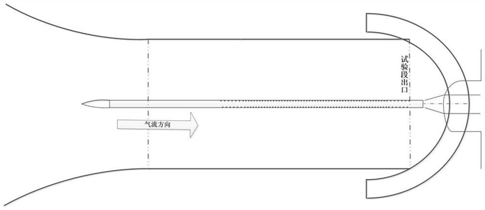
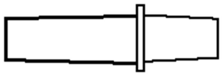
[0024] The overall length of the axial static pressure detection tube in this embodiment is 1.8m, L:D=8:1, see figure 2 , the supporting mechanism is as image 3 Straight header shown.

[0025] The method for measuring the length of the interference zone of the transonic wind tunnel support system in this embodiment includes the following steps:

[0026] a. Install the axial detection bent frame on the middle bracket of the transonic wind tunnel, start the transonic wind tunnel at the Mach number Ma=0.3, move the axial detection bent frame according to the preset path, change the measurement position until the measurement Complete, close the transonic wind tunnel, obtain the Mach number distribution of the core flow field of the transonic wind tunnel with Mach number 0.3 after data processing, and obtain the flow calibration results of the transonic wind tunnel;

[0027] b. Remove the axial detection bent frame, install the direct head, and install the axial static pressure...

Embodiment 2

[0034] The implementation of this embodiment is basically the same as that of Embodiment 1, the main difference is that the supporting mechanism is as Figure 4 The length of the interference zone obtained for the dual-shaft system joint shown is shown in Table 1.

Embodiment 3

[0036] The implementation of this embodiment is basically the same as that of Embodiment 1, the main difference is that the supporting mechanism is as Figure 5 The length of the interference zone obtained for the optimized dual-axis joint shown in Table 1.

[0037] Table 1 Test results of interference zone length for different support systems

[0038] Ma 0.3 0.4 0.5 0.6 0.7 0.8 0.9 0.95 1.0 Flow Field Calibration 1.20 1.45 1.60 1.60 1.60 1.60 1.60 1.60 1.30 straight head 1.58 1.64 1.73 1.76 1.76 1.79 1.94 1.94 1.79 Dual Shaft System Connector 1.73 1.85 1.94 2.00 2.21 2.21 2.21 2.15 1.94 Optimized dual shaft system joint 1.64 1.73 1.79 1.85 1.85 1.94 2.00 2.00 1.79


PUM


Abstract

The invention discloses a method for measuring the length of an interference area of a transonic wind tunnel support system. According to the measuring method, Mach number distribution of the centralaxis of a transonic wind tunnel test section is measured through an axial static pressure detection tube and compared with a flow calibration result; and the Mach number deviation 0.005 at the same position is taken as a reference, and when the Mach number deviation at the same position exceeds 0.005, it is considered that the position is interfered by the support system, and the distance S from the current position to the outlet of the transonic wind tunnel test section is measured, wherein S is the length of the interference area. The measuring device used in the measuring method is simple and reliable in structure, convenient to operate and good in repeatability, has high adaptability and high application value, and has important significance in improving the transonic wind tunnel testquality and optimizing the design of a model supporting mechanism.

Description

technical field [0001] The invention belongs to the technical field of transonic wind tunnel tests, and in particular relates to a method for measuring the length of an interference zone of a support system of a transonic wind tunnel. Background technique [0002] In the transonic wind tunnel test, the model is installed on the middle support of the transonic wind tunnel through the support system. In the wind tunnel test, different support systems are selected according to the requirements of the task. In the conventional force measurement and pressure measurement test, the direct head or the double shaft are generally used. The system supports the model, and then combines the angle of attack system of the transonic wind tunnel to realize the change of the model attitude, and then completes the aerodynamic force measurement or pressure measurement of the model. [0003] Through the sorting and inductive analysis of the test data over the years, it can be found that the supp...

Claims


Application Information

Patent Timeline
Patent Type & Authority Applications(China)
IPC IPC(8): G01M9/02G01M9/06
CPCG01M9/02G01M9/06
Inventor 王瑞波吴军强杨可张林蒋鸿魏志钟世东刘光远陈学孔杨洋贾智亮林学东赵莉谢艳
Owner INST OF HIGH SPEED AERODYNAMICS OF CHINA AERODYNAMICS RES & DEV CENT
Why Eureka
Try Eureka