Color-changing device and control method thereof

A technology of color-changing devices and color-changing layers, applied in instruments, nonlinear optics, optics, etc., can solve problems such as large current loss and device damage, and achieve the effect of reducing current loss

Active Publication Date: 2021-03-26
SHENZHEN GUANGYI TECH CO LTD
View PDF10 Cites 1 Cited by
  • Summary
  • Abstract
  • Description
  • Claims
  • Application Information

AI Technical Summary

Problems solved by technology

In this way, the current loss of directly applying different voltages on the same bus bar is also large, and the excessive current loss will be converted into heat energy, thereby accelerating the damage of the electrochromic device, especially the damage of the device at the bus bar

Method used


Image

  • Color-changing device and control method thereof
  • Color-changing device and control method thereof
  • Color-changing device and control method thereof

Examples


Embodiment 1

[0073] This embodiment provides a color-changing device. The color-changing device can realize the effect of color changing in different regions, and can also realize the effect of changing color gradually.

[0074] The color-changing device includes a first base layer, a first conductive layer, a color-changing layer, a second conductive layer and a second base layer which are sequentially stacked;

[0075] The color-changing layer includes: an ion storage layer, an ion transfer layer, and an electrochromic layer stacked in sequence, and the electrochromic layer is stacked to the first conductive layer;

[0076] like Figure 4 As shown, the two ends of the first conductive layer are provided with positioning holes 12 on the first conductive layer; Figure 5 As shown, the two ends of the second conductive layer are provided with positioning holes 22 on the second conductive layer;

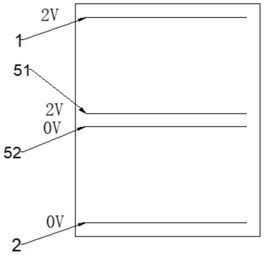
[0077] like figure 1 As shown, a first bus bar 1 and a second bus bar 2 are respectively ar...

Embodiment 2

[0086] This embodiment provides a control method for a color-changing device, and the control method can be executed by a controller that controls the transmittance of the color-changing device. Specifically, it includes the following steps:

[0087] S1. Apply a color-changing control signal to the color-changing device, and determine a target voltage according to the transmittance state type carried by the color-changing control signal received by the color-changing device, where the target voltage at least includes the first bus bar, Voltage values ​​corresponding to the second bus bar, the third bus bar, the fourth bus bar, the boundary bus bar and the partition bus bar respectively;

[0088] S2. Adjust the transmittance state of the color changing device with the target voltage.

[0089] Wherein, in the above step S1, the discoloration control signal may be applied by the user autonomously, or may be triggered by specific conditions (such as temperature, illumination, etc...

Embodiment 3

[0105] This embodiment provides a color changing device that can realize both zoned color changing and gradual color changing.

[0106] The color-changing device includes a first base layer, a first conductive layer, a color-changing layer, a second conductive layer and a second base layer that are stacked in sequence;

[0107] A first bus bar 1 and a second bus bar 2 are respectively disposed at the edges of both ends of the first conductive layer;

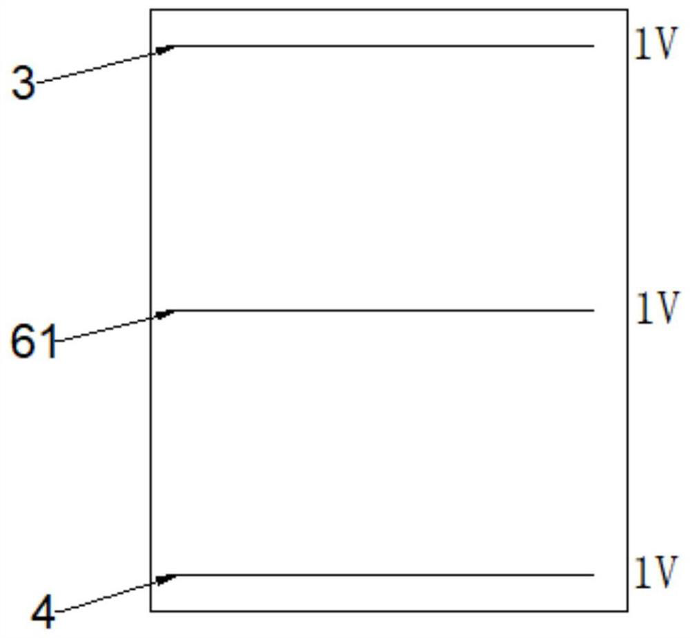
[0108] A third bus bar 3 and a fourth bus bar 4 are respectively disposed at the edges of both ends of the second conductive layer;

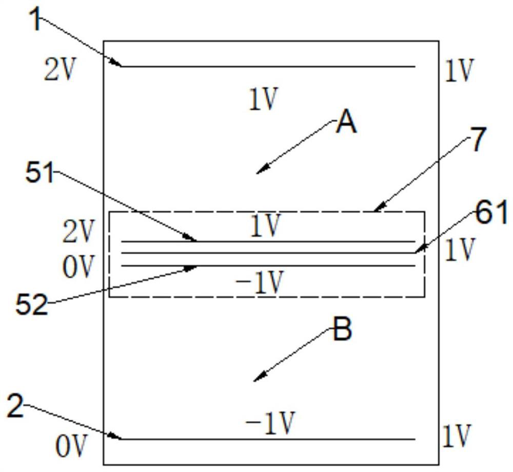
[0109] like Figure 7 As shown, the color-changing device includes a second partition structure 8 and a third partition structure 9, and the second partition structure 8 includes a first boundary bus bar 51, a second boundary bus bar 52 and a The first partition bus bar 61 located on the second conductive layer; the first partition bus bar 61 is between the first boundary bus bar 51 and the secon...


PUM

PropertyMeasurementUnit
Widthaaaaaaaaaa
Thicknessaaaaaaaaaa
Widthaaaaaaaaaa

Abstract

The invention provides a color changing device and a control method thereof. The color changing device comprises a first substrate layer, a first conducting layer, a color changing layer, a second conducting layer and a second substrate layer which are sequentially arranged in a stacked mode. The color changing device comprises at least one partition structure, the partition structure comprises atleast two boundary bus bars and at least one partition bus bar located between the two boundary bus bars, and the partition bus bars and the boundary bus bars are located on different conducting layers respectively. The partition structure composed of the partition bus bars and the boundary bus bars is additionally arranged on the conducting layer of the color-changing device, the voltage on thebus bars is regulated and controlled, the color-changing areas of the color-changing device are adjusted according to actual application, meanwhile, the effect of combining gradient and partition is achieved, and device damage caused by current loss is reduced.

Description

technical field [0001] The invention belongs to the technical field of electrochromism, and relates to a color-changing device and a control method thereof. Background technique [0002] How to control the zonal discoloration of electrochromic devices (that is, the case where the transmittances of different regions are inconsistent) is the focus of electrochromic products. Generally, the conductive layers of different regions are separated to realize the control of different regions. However, in the prior art, once the conductive layers are separated, the discolored regions are fixed and cannot be adjusted according to the needs of practical applications. [0003] At the same time, the electrochromic device can further adjust the light intensity by adjusting the transmittance of the device. Usually, the entire electrochromic device is in a specific transmittance state, that is, the transmittance of each point on the device is the same, and a graded state cannot be achieved...

Claims


Application Information

Patent Timeline
IPC IPC(8): G02F1/161G02F1/163
CPCG02F1/161G02F1/163G02F1/155G02F1/1516G02F1/1533G09G3/38G09G2310/0248G09G2320/0626G09G2320/0666
Inventor 王巍舒
Owner SHENZHEN GUANGYI TECH CO LTD
Why Eureka
Try Eureka