Button cell packaging structure and button cell

A button battery, packaging structure technology, applied in the direction of cylindrical shell batteries/batteries, batteries, structural parts, etc., can solve the problems of increasing the thickness or width of button batteries, affecting battery performance, and damaging battery cells, and improving power storage. The volume, the appearance is exquisite and beautiful, and the effect of preventing the short circuit of the battery

Pending Publication Date: 2021-03-26
惠州市超聚电池有限公司
View PDF0 Cites 4 Cited by
  • Summary
  • Abstract
  • Description
  • Claims
  • Application Information

AI Technical Summary

Problems solved by technology

Since the traditional packaging method adopts a mechanical fit method, which requires high processing accuracy, it is prone to liquid leakage caused by poor sealing effect. The connection structure between the negative electrode casings needs to occupy a large space, and the space utilization rate is low, which leads to an increase in the thickness or width of the button battery, which is not conducive to the miniaturization of the button battery.
[0004] In order to prevent the short circuit of the battery caused by the contact between the negative electrode cover and the shell, the traditional button battery uses an insulating sealing ring to cover the outer edge of the negative electrode cover, while the upper edge of the shell is folded and buckled the outer edge of the insulating sealing ring. The packaging of the button battery is completed. However, during the process of turning over the upper edge of the shell and buckling the outer edge of the insulating sealing ring, the shell is likely to come into contact with the negative electrode cover, resulting in a short circuit of the battery and damage to the battery cell. damage, thereby affecting the performance of the battery

Method used


Image

  • Button cell packaging structure and button cell
  • Button cell packaging structure and button cell
  • Button cell packaging structure and button cell

Examples


Embodiment Construction

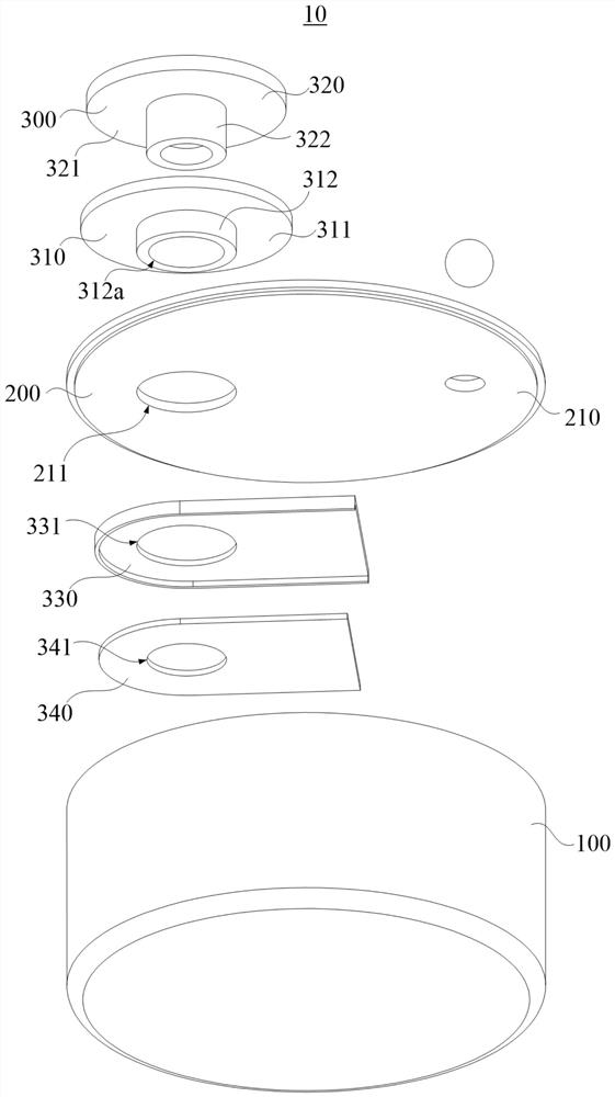
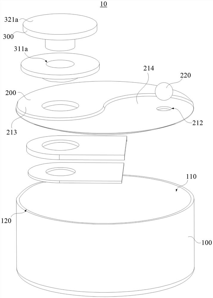
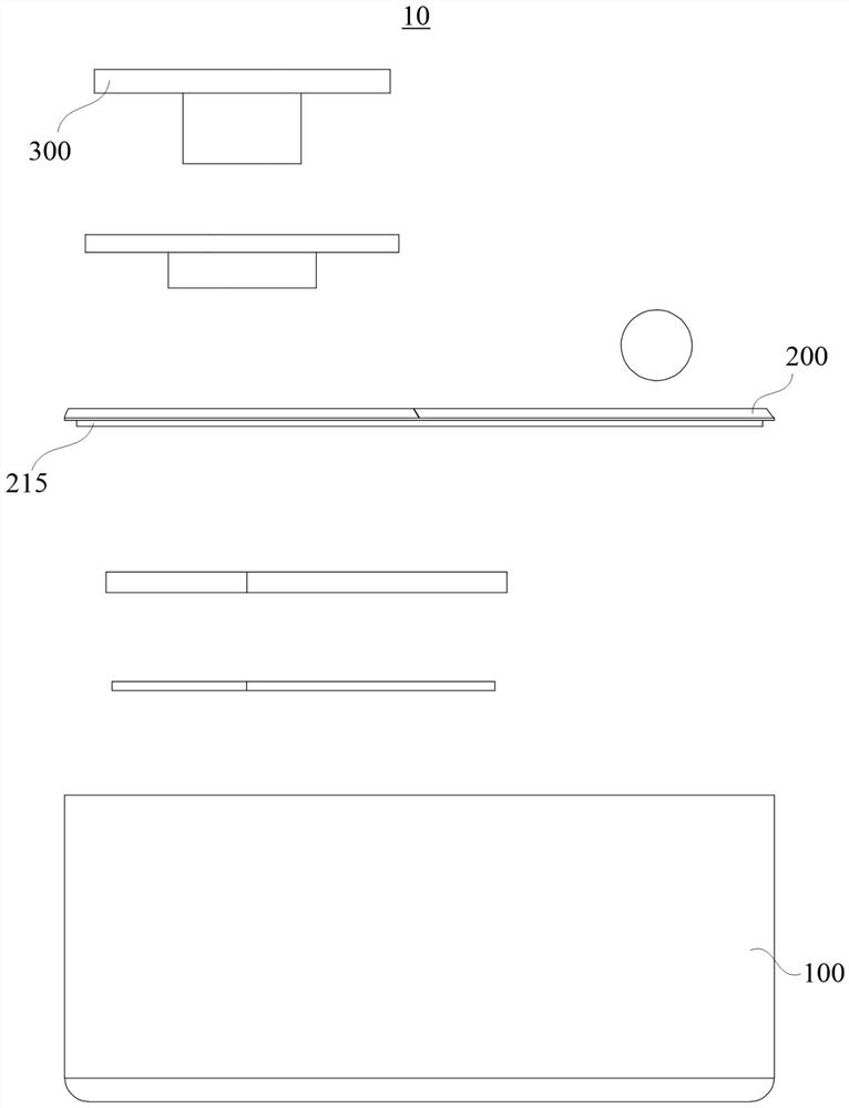
[0027] In order to facilitate the understanding of the present invention, the present invention will be described more fully below with reference to the associated drawings. Preferred embodiments of the invention are shown in the accompanying drawings. However, the present invention can be embodied in many different forms and is not limited to the embodiments described herein. On the contrary, the purpose of providing these embodiments is to make the disclosure of the present invention more thorough and comprehensive.

[0028] It should be noted that when an element is referred to as being “fixed” to another element, it can be directly on the other element or there can also be an intervening element. When an element is referred to as being "connected to" another element, it can be directly connected to the other element or intervening elements may also be present. The terms "vertical," "horizontal," "left," "right," and similar expressions are used herein for purposes of ill...


PUM


Abstract

The invention provides a button cell packaging structure and a button cell. The button cell packaging structure comprises a shell, a top cover assembly and a negative electrode connecting assembly. The shell is provided with an installation cavity and a shell opening, and the installation cavity is communicated with the shell opening. The top cover assembly comprises a cover body, the cover body is welded to the shell so that the cover body can cover the opening of the shell, and a cover hole is formed in the cover body. The negative electrode connecting assembly comprises an insulating separator and a negative electrode contact piece, the insulating separator comprises an insulating spacer and an insulating protruding part, the insulating spacer is provided with a first through hole, theprotruding part is provided with a second through hole, the insulating spacer is connected with the insulating protruding part, and the first through hole is communicated with the second through hole.Due to the fact that the cover body and the shell are welded, the installation cavity is in a fully-closed state, compared with a traditional mechanical packaging mode, a mechanical packaging structure does not need to be additionally arranged, the installation cavity can be used for installing a battery cell with larger electric quantity, the power supply storage capacity of the button cell is effectively improved, and miniaturization development of the button cell is facilitated.

Description

technical field [0001] The invention relates to the technical field of button batteries, in particular to a button battery packaging structure and a button battery. Background technique [0002] With the development of portable electronic products and smart wearable electronic products, batteries are required to be more miniaturized. While maintaining a high service life, the battery is required to have as high a volume specific energy and a mass specific energy as possible, so the demand for lithium-ion button batteries is also increasing day by day. [0003] The traditional button battery usually adopts the following two packaging methods. One is that the positive and negative shells of the button battery are fastened to each other through the difference in inner diameter, and are fixedly connected through the slots at the joints of the upper and lower shells; Fold the upper edge of the casing, so that the upper edge of the casing buckles the negative electrode cover, and...

Claims


Application Information

Patent Timeline
Patent Type & Authority Applications(China)
IPC IPC(8): H01M10/04H01M50/109H01M50/153H01M50/169H01M50/586H01M50/593
CPCH01M10/0427H01M10/0431H01M2220/30Y02E60/10Y02P70/50
Inventor 刘彪劳华亮王坤
Owner 惠州市超聚电池有限公司
Why Eureka
Try Eureka