Direct-current microgrid energy regulation and control method for grouping and optimizing storage battery units
What is Al technical title?
Al technical title is built by PatSnap Al team. It summarizes the technical point description of the patent document.
A DC microgrid, battery technology, applied in parallel operation of DC power supply, load balancing in DC network, etc., can solve problems such as reducing cycle life
Active Publication Date: 2021-03-26
JIANGMEN POWER SUPPLY BUREAU OF GUANGDONG POWER GRID
View PDF9 Cites 1 Cited by
Summary
Abstract
Description
Claims
Application Information
AI Technical Summary
This helps you quickly interpret patents by identifying the three key elements:
Problems solved by technology
Method used
Benefits of technology
Problems solved by technology
Due to its own characteristics, the non-ideal power storage system in actual production, its cycle life and operating efficiency are greatly affected by unavoidable factors such as frequent charge-discharge conversion times and system operation modes, especially frequent charge-discharge conversion, will Greatly reduce its cycle life
Method used
Image
Click on the blue label to locate the original text in one second.
Reading with bidirectional positioning of images and text.
Examples
no. 1 example
[0045] Such as Figure 1 to Figure 6 Shown is a first embodiment of a DC microgrid energy regulation method for grouping and optimizing battery cells according to the present invention, which includes the following steps:
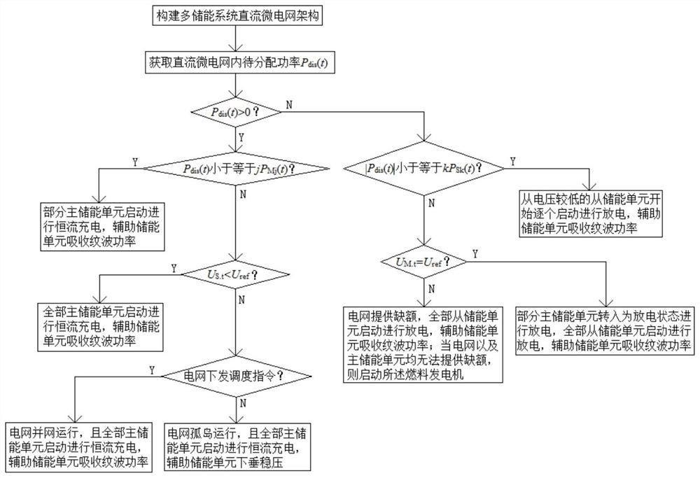
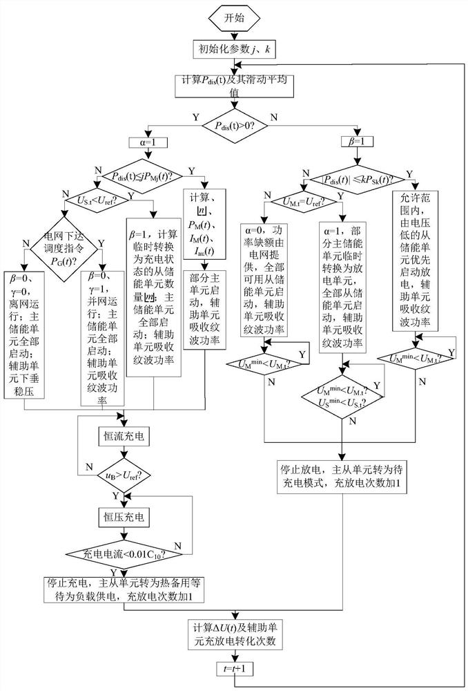
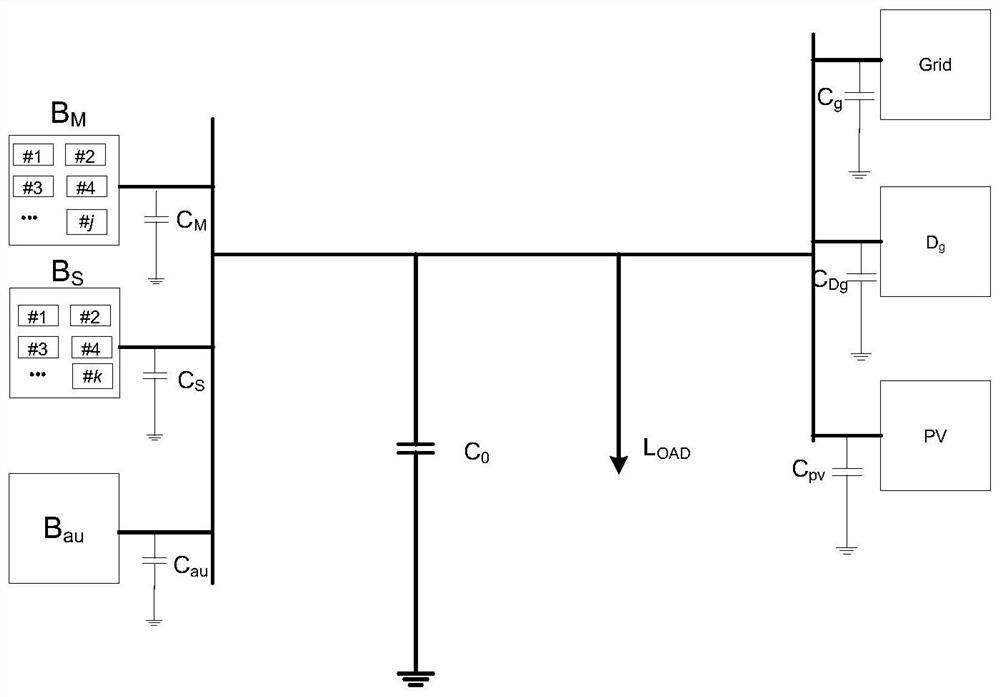
[0046] S1. Build a DC microgrid architecture with multiple energy storage systems;
[0047] Such as image 3 As shown, the multi-energy storage system DC microgrid architecture includes the main energy storage unit B M , from energy storage unit B S , Auxiliary energy storage unit B au , Grid G rid , fuel generator D g , Photovoltaic unit P V ;Main energy storage unit B M Absorbed photovoltaic unit power P PV (t), from energy storage unit B S Provide power for the load, auxiliary energy storage unit B au Absorb the disturbance power on the DC bus; in addition, Load represents the DC microgrid load.
[0048] In order to enable the DC microgrid to optimally allocate system power, taking into account the maximum utilization of energy and the economy...
PUM
Abstract
The invention relates to the technical field of direct-current micro-grids, in particular to a direct-current microgrid energy regulation and control method for grouping and optimizing storage batteryunits. The method comprises the following steps: S1, constructing framework; S2, acquiring Pdis (t), executing S3 if the Pdis(t) is larger than 0, and otherwise, executing S6; S3, if Pdis (t) is smaller than or equal to jPMj (t), starting part of the main energy storage units; otherwise, executing S4; S4, if US.t is less than Uref, starting all the main energy storage units, and if not, executingS5; S5, if the power grid issues an instruction, carrying out grid-connected operation, and starting all main energy storage units; otherwise, carrying out island operation, starting all the main energy storage units, and assisting the energy storage units in drooping and stabilizing voltages; S6, if |Pdis(t)| is smaller than or equal to kPSk(t), starting the energy storage units one by one; otherwise, executing S7; S7, if UM.t is equal to Uref, discharging part of the main energy storage units, and starting all slave energy storage units; otherwise, executing S8; and S8, enabling the power grid to provide a vacancy and starting all slave energy storage units; and when the power grid and the main energy storage units cannot provide the vacancy, starting a fuel generator. According to theinvention, the system power can be optimally distributed, and the maximum utilization of energy and the economy of the system are both considered.
Description
technical field [0001] The present invention relates to the technical field of DC micro-grid, and more specifically, to a DC micro-grid energy control method for grouping and optimizing storage battery units. Background technique [0002] In order to be more friendly to accept new energy dominated by intermittent and uncertainties, DC micro-grids came into being. Compared with traditional AC large grids, DC micro-grids are vulnerable to power fluctuations of distributed energy sources, making the instantaneous power of the system The balance of the DC microgrid is destroyed, which is undoubtedly a problem for loads with high power quality requirements. Therefore, resisting random fluctuations in power is a must-have capability for the development of DC microgrids. The battery has a strong power adjustment capability, which can provide strong support for the stable operation of the DC microgrid, and can also flexibly configure capacity according to the scale of the DC microgr...
Claims
Application Information
Patent Timeline
Application Date:The date an application was filed.
Publication Date:The date a patent or application was officially published.
First Publication Date:The earliest publication date of a patent with the same application number.
Issue Date:Publication date of the patent grant document.
PCT Entry Date:The Entry date of PCT National Phase.
Estimated Expiry Date:The statutory expiry date of a patent right according to the Patent Law, and it is the longest term of protection that the patent right can achieve without the termination of the patent right due to other reasons(Term extension factor has been taken into account ).
Invalid Date:Actual expiry date is based on effective date or publication date of legal transaction data of invalid patent.
Patent Type & Authority Applications(China)
IPC IPC(8): H02J1/14H02J1/10
CPCH02J1/14H02J1/10Y02E10/56
Inventor 闫海明黄伟杰宋涛张云飞
Owner JIANGMEN POWER SUPPLY BUREAU OF GUANGDONG POWER GRID