Textile wastewater filtering method

A technology of textile wastewater and filtration method, applied in the textile field, can solve the problems of high cost, unsatisfactory efficiency and effect, low desorption efficiency and the like

Inactive Publication Date: 2021-03-30
台州市涌星贸易有限公司
View PDF0 Cites 2 Cited by
  • Summary
  • Abstract
  • Description
  • Claims
  • Application Information

AI Technical Summary

Problems solved by technology

In addition to the large amount of water, because the textile wastewater is mostly the sewage of washing and dyeing of cloth, thread, etc., the interior contains a lot of wool fiber impurities. The interception of wool fiber is relatively simple, but after being intercepted, it is more complicated to be entangled on the interceptor, which makes it very difficult for the staff to clean up the entangled wool fiber, and the desorption efficiency is low, which affects the overall efficiency of waste water treatment. Furthermore, the existing equipment cannot operate continuously, and the maintenance cycle is short, especially the cleaning of interception mechanisms such as filter screens is very frequent, while the waste water is continuously generated, resulting in the need for multi-step and multi-set equipment switching operations in the waste water treatment process , not only the cost is high, but also the efficiency and effect are not ideal

Method used


Image

  • Textile wastewater filtering method
  • Textile wastewater filtering method
  • Textile wastewater filtering method

Examples


Embodiment Construction

[0030] The following are specific embodiments of the present invention and in conjunction with the accompanying drawings, the technical solutions of the present invention are further described, but the present invention is not limited to these embodiments.

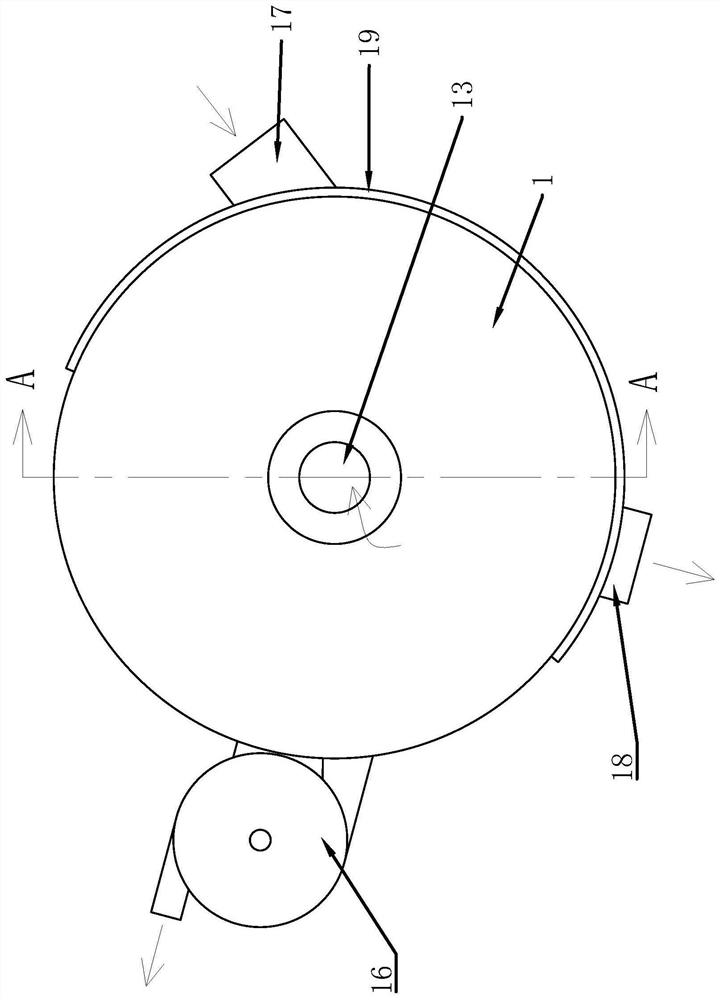
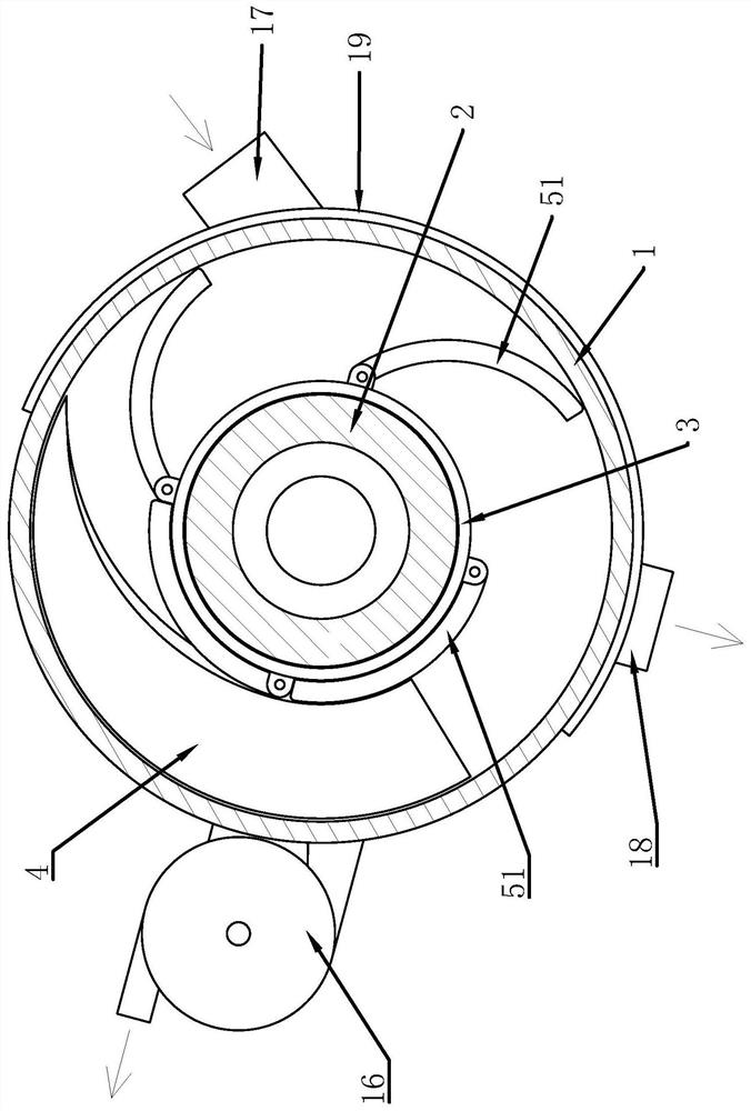
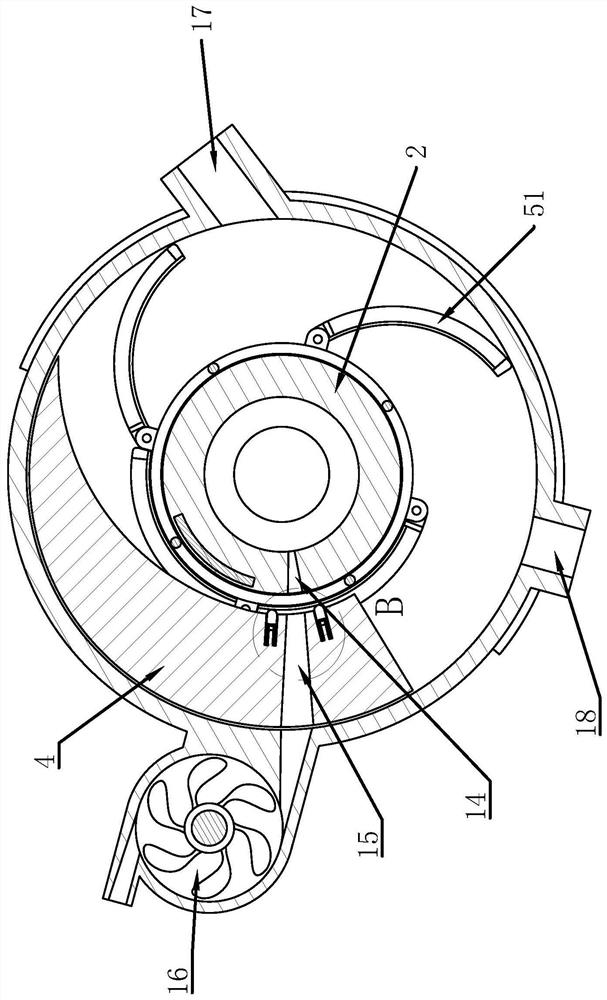
[0031] Such as Figure 1 to Figure 9 As shown, it includes a cylindrical housing 1, a positioning cylinder 2 fixedly connected to the housing 1, a swivel 3 rotatably connected to the outside of the positioning cylinder 2, and a limit guide block 4 fixed on the inner wall of the housing 1. The housing 1 and the positioning cylinder 2 form an annular water storage chamber 11, the swivel 3 is driven by a geared motor 12, and a number of arc-shaped installation frames 51 are hinged outside the swivel 3, and a filter screen 52 is installed in the middle of the installation frame 51 , the hinge points of each mounting frame 51 and the swivel 3 are evenly distributed circumferentially on the outer wall surface of the swivel 3, an...


PUM


Abstract

The invention provides a textile wastewater filtering method, and belongs to the technical field of textiles. Wherein when waste water with the small residue chip concentration is treated, a gear motor is firstly started to enable all rotating rings to slowly rotate in the direction opposite to the water flow direction, the rotating speed of the rotating rings is suitable for enabling the waste water not to enter the position where a limiting guide block is located as much as possible, and horizontal-flow textile waste water is conveyed into a water inlet connecting pipe; after the sensor is triggered at any position, a negative pressure pump is started, supply of waste water is suspended, a heating piece is powered on, fabric scraps adhering to the filter screens are burnt at high temperature to form scraps, the scraps are pumped away from the filter screens under the action of negative pressure, water is supplied again after the filter screens are cleaned multiple times, the negativepressure pump is turned off, and the heating piece is powered off; and when the wastewater with relatively high residue and scrap concentration is treated, the filter screen is cleaned in a state ofsuspending water supply. The method has the advantages of high efficiency and the like.

Description

technical field [0001] The invention belongs to the technical field of textiles and relates to a method for filtering textile wastewater. Background technique [0002] The textile process produces a large amount of wastewater, including printing and dyeing wastewater, chemical fiber textile wastewater, degumming and wool washing wastewater, etc. Among them, printing and dyeing wastewater and chemical fiber textile wastewater are the most polluted. The textile printing and dyeing industry is one of the industrial sectors that consume a lot of water and discharge a lot of wastewater. In addition to the large amount of water, because the textile wastewater is mostly the sewage of washing and dyeing of cloth, thread, etc., the interior contains a lot of wool fiber impurities. The interception of wool fiber is relatively simple, but after being intercepted, it is more complicated to be wound on the intercepted object, which makes it very difficult for the staff to clean up the w...

Claims


Application Information

Patent Timeline
Patent Type & Authority Applications(China)
IPC IPC(8): B01D29/03B01D29/54B01D29/60B01D29/76B01D29/84B01D29/90B01D37/00
CPCB01D29/035B01D29/54B01D29/60B01D29/76B01D29/84B01D29/906B01D37/00
Inventor 林晓丽林友富蔡珉
Owner 台州市涌星贸易有限公司
Why Eureka
Try Eureka