
Material injection device for die-casting equipment

An equipment and material chamber technology, applied in the field of material injection devices, can solve the problems of reducing the completion degree of material injection, easy damage to mechanical structure, low speed and precision, etc., to improve stability and accuracy, reduce mechanical damage, speed and precision. high precision effect

Pending Publication Date: 2021-03-30
DONGGUAN TECH-CASTING CO LTD
View PDF0 Cites 0 Cited by
  • Summary
  • Abstract
  • Description
  • Claims
  • Application Information

AI Technical Summary

Problems solved by technology

[0004] (1) The hydraulic cylinder is used as the power source of the injection material. Due to the limitations of the hydraulic cylinder, the speed and accuracy of the action stroke are relatively low, which affects the stability and accuracy of the injection operation.
[0005] (2) In the injection device, the push-down mechanism and the injection plunger of the injection mechanism are rigidly connected, not only the mechanical structure is easily damaged, but also when the injection is made, it is not known when the mold cavity can Filling, that is, it is impossible to know the time point when the mold cavity is filled; at the same time, there is no guarantee that the stroke of the press can fill the mold cavity
As a result, the degree of completion of the shot is reduced
[0006] (3) In the material chamber of the injection device, the piston that controls the feeding is a simple piston structure that only includes a slope, and moves up and down entirely by air pressure without a guiding structure, which causes the piston to easily shift left and right during the up and down movement , unstable phenomenon; at the same time, only rely on the slope to seal the feed port, low stability

Method used


Image

  • Material injection device for die-casting equipment
  • Material injection device for die-casting equipment
  • Material injection device for die-casting equipment

Examples


Embodiment Construction

[0037] In order to further illustrate the technical means and functions adopted by the present invention to achieve the intended purpose, the specific implementation modes of the present invention will be described in detail below in conjunction with the accompanying drawings and preferred embodiments.

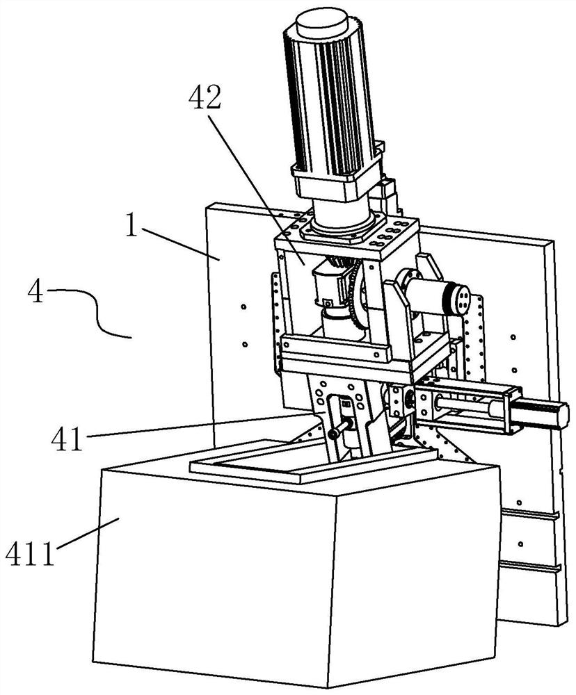
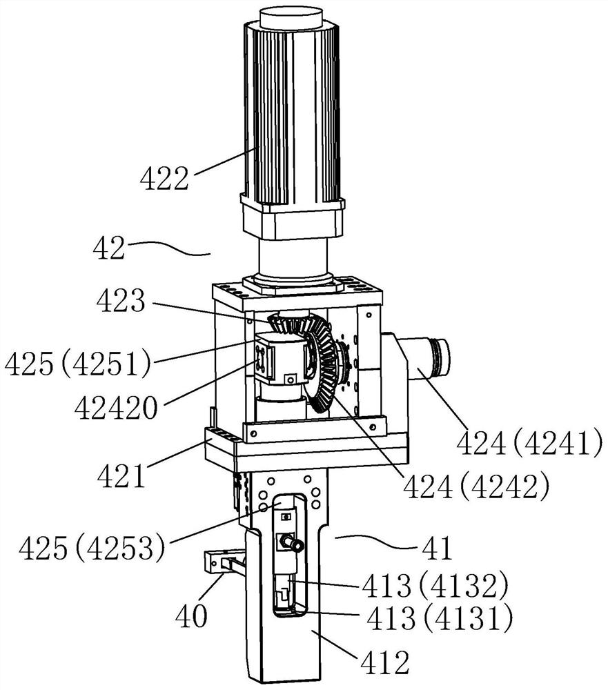
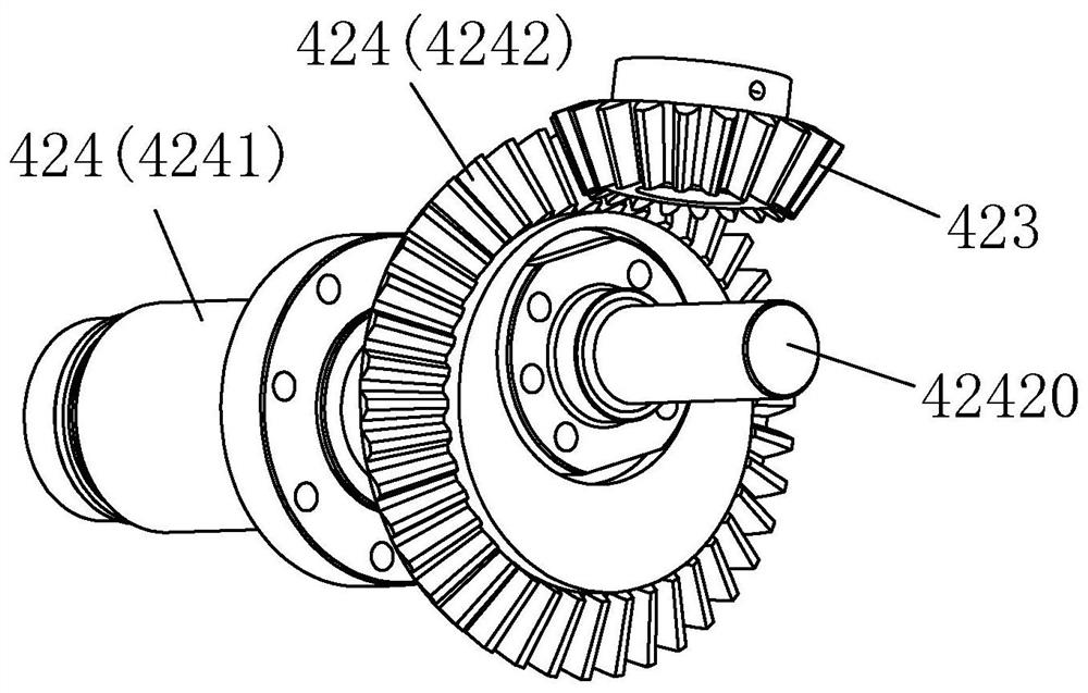
[0038] Please refer to figure 1 and figure 2 , the embodiment of the present invention provides a injection device 4 for die-casting equipment, including a injection mechanism 41 arranged on the back of the longitudinal mounting plate 1, and a longitudinal push mechanism 42 connected to the injection mechanism 41, wherein, like figure 2 As shown, the longitudinal push mechanism 42 includes a longitudinal push mount 421, a longitudinal push servomotor 422 arranged on the longitudinal push mount 421, a drive gear 423 connected to the output shaft of the longitudinal push servomotor 422, and a horizontally disposed An eccentric wheel structure 424 on the longitudinal pushing ...


PUM


Abstract

The invention discloses a material injection device for die-casting equipment. A material injection mechanism and a longitudinal pushing mechanism connected to the material injection mechanism are included. The longitudinal pushing mechanism comprises a longitudinal pushing installation base, a longitudinal pushing servo motor arranged on the longitudinal pushing installation base, a driving gearconnected to an output shaft of the longitudinal pushing servo motor, an eccentric wheel structure transversely arranged on the longitudinal pushing installation base and engaged with the driving gear, and a longitudinal pushing structure longitudinally arranged on the longitudinal pushing installation base and connected to the eccentric wheel structure. The material injection mechanism comprisesa smelting furnace, a material injection mounting base arranged on the smelting furnace, a material injection nozzle transversely inserted into the material injection installation base, and a materialinjection pushing assembly arranged in the material injection installation base and connected to the longitudinal pushing structure. The material injection device for the die-casting equipment is high in material injection stability and accuracy, and material injection filling saturation can be guaranteed.

Description

technical field [0001] The invention relates to the technical field of die-casting, in particular to a material injection device for die-casting equipment. Background technique [0002] Die casting is a precision casting method that uses high pressure to force molten metal into a complex-shaped metal mold. A die-casting machine is a machine used for die-casting. Under pressure, the die-casting machine hydraulically injects molten metal into a mold for cooling and forming. After the mold is opened, a solid metal casting can be obtained. [0003] The traditional die casting machine has the following disadvantages: [0004] (1) The hydraulic cylinder is used as the power source for injection. Due to the limitations of the hydraulic cylinder, the speed and accuracy of its action stroke are relatively low, which affects the stability and accuracy of the injection operation. [0005] (2) In the injection device, the push-down mechanism and the injection plunger of the injection ...

Claims


Application Information

Patent Timeline
Patent Type & Authority Applications(China)
IPC IPC(8): B22D17/20
CPCB22D17/203
Inventor 吕学勳
Owner DONGGUAN TECH-CASTING CO LTD
Learn More