Self-adjusting fixture for laser chips

A self-adjusting, chip technology, applied in the direction of manufacturing tools, workpiece clamping devices, etc., can solve the problems of easy deviation of the chip and unstable clamping, so as to improve the processing efficiency and accuracy, reduce the difficulty of processing and testing, and smooth the thrust. Effect

Active Publication Date: 2022-05-24
STELIGHT INSTR CO LTD
View PDF5 Cites 0 Cited by
  • Summary
  • Abstract
  • Description
  • Claims
  • Application Information

AI Technical Summary

Problems solved by technology

[0004] The purpose of the present invention is to provide a self-adjusting jig for laser chips, which solves the problems in the prior art that when the chip position is fixed by vacuuming to form a negative pressure, the chip is prone to shift and the clamping is unstable.

Method used


Image

  • Self-adjusting fixture for laser chips
  • Self-adjusting fixture for laser chips
  • Self-adjusting fixture for laser chips

Examples


Embodiment 1

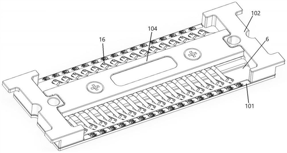
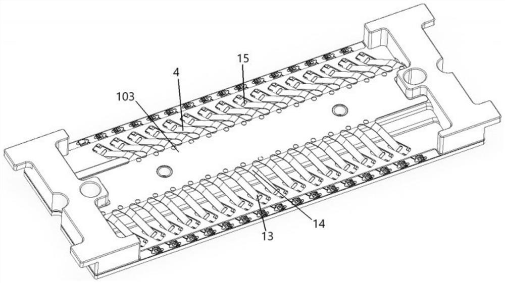
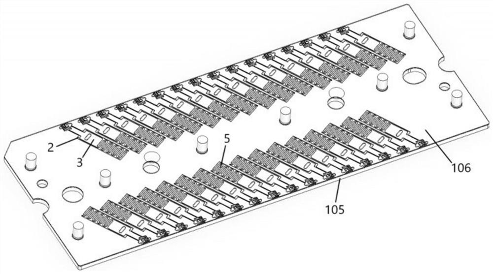
[0025] Example 1: A self-adjusting fixture for laser chips, refer to the attached Figures 1~4 , including a positioning slot 1 and a bar-shaped slot 2 opened on the top surface of the base 101, the positioning slot 1 is communicated with the bar-shaped slot 2 and is used for placing chips, and a positioning plate 3 is movably installed in the bar-shaped slot 2. This positioning The front end of the plate 3 is provided with a right-angle positioning notch 12, the positioning groove 1 has a positioning right-angle 11, the two sides of the right-angle positioning notch 12 are in extrusion contact with the adjacent two sides of the chip, and the two sides of the positioning right angle 11 are in contact with the other two sides of the chip. touch;

[0026] The base 101 is provided with a strip block 102, a spring plate 103 and a pressure plate 104, the strip block 102 is located on the top surface of the base 101, the spring plate 103 is installed on the strip block 102, and the ...

Embodiment 2

[0029] Example 2: A self-adjusting fixture for laser chips, refer to the attached Figures 1~4 , including a positioning slot 1 and a bar-shaped slot 2 opened on the top surface of the base 101, the positioning slot 1 is communicated with the bar-shaped slot 2 and is used for placing chips, and a positioning plate 3 is movably installed in the bar-shaped slot 2. This positioning The front end of the plate 3 is provided with a right-angle positioning notch 12, the positioning groove 1 has a positioning right-angle 11, the two sides of the right-angle positioning notch 12 are in extrusion contact with the adjacent two sides of the chip, and the two sides of the positioning right angle 11 are in contact with the other two sides of the chip. touch;

[0030] The base 101 is provided with a strip block 102, a spring plate 103 and a pressure plate 104, the strip block 102 is located on the top surface of the base 101, the spring plate 103 is installed on the strip block 102, and the ...


PUM


Abstract

The invention discloses a self-adjusting fixture for laser chips, which includes a positioning groove and a bar-shaped groove provided on the top surface of a base. The positioning groove communicates with the bar-shaped groove and is used for placing chips. The front end of the positioning plate is provided with a right-angle positioning notch, the positioning groove has a positioning right angle, the two sides of the right-angle positioning notch are in extrusion contact with the adjacent two sides of the chip, and the two sides of the positioning right angle are in contact with the other two sides of the chip; An elastic piece is also installed in the strip groove, and this elastic piece is connected with the rear end of the positioning plate, and when the elastic piece is in a relaxed state, the front end of the positioning plate is separated from the chip; the base is covered with a limiting plate, so that The positioning plate is located between the limiting plate and the base. The invention can not only reduce the difficulty of processing and testing, improve the processing efficiency and precision, but also enable the chip to be placed in the positioning groove in a horizontal state, avoiding the adverse effects of chip warping on the processing accuracy and clamping stability.

Description

technical field [0001] The invention relates to a self-adjusting clamp for laser chips, belonging to the technical field of chips. Background technique [0002] When making a laser chip, not only the chip body needs to be mounted on the ceramic substrate, but also the chip body and the ceramic substrate need to be connected by gold wires, and the chip needs to be photoelectrically tested; therefore, in order to achieve efficient chip production, it is necessary to Chips are fixed in fixtures, and are processed and tested in batches using equipment such as placement, gold wire bonding, etc. [0003] At present, there is a chip fixing fixture on the market, which can temporarily fix the chip through the chip groove and the vacuum hole in the chip groove. However, due to the small size of the chip applied to the laser, in the actual operation process, not only the vacuum pump The vacuum hole is easy to block, and during the placement, processing and transfer of the chip in dif...

Claims


Application Information

Patent Timeline
Patent Type & Authority Patents(China)
IPC IPC(8): B25B11/00
CPCB25B11/00
Inventor 罗跃浩黄建军胡海洋
Owner STELIGHT INSTR CO LTD
Why Eureka
Try Eureka