Automatic lens production device

A production device and lens technology, applied in glass molding, application, glass manufacturing equipment, etc., can solve the problems of not being able to eliminate the internal stress of the lens, and achieve the effect of easy collection

Pending Publication Date: 2021-03-30
CHONGQING JINGCHENMEI TECH CO LTD
View PDF7 Cites 1 Cited by
  • Summary
  • Abstract
  • Description
  • Claims
  • Application Information

AI Technical Summary

Problems solved by technology

[0004] In order to overcome the shortcomings of the existing technology that the stock solution needs to be manually heated by a heater and the internal stress in the lens cannot be better eliminated, the technical problem of the present invention is to provide a method that can heat the stock solution while cutting the material and can eliminate the internal stress in the lens. Automated lens production device for internal stress in lenses

Method used


Image

  • Automatic lens production device
  • Automatic lens production device
  • Automatic lens production device

Examples


Embodiment 1

[0036] An automated lens production device, such as figure 1 , figure 2 , image 3 , Figure 4 and Figure 5 As shown, it includes a base 1 , a discharge mechanism 2 and a heating mechanism 3 , the base 1 is provided with the discharge mechanism 2 , and the base 1 is provided with the heating mechanism 3 .

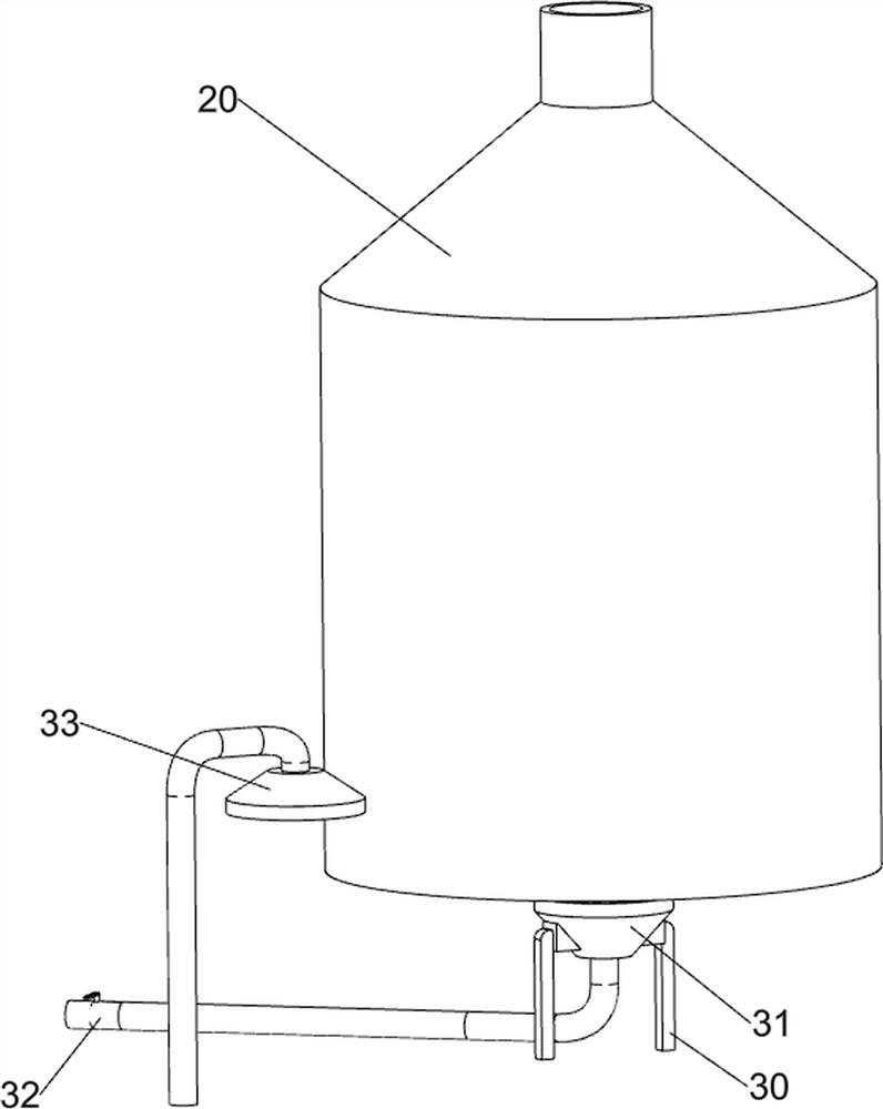
[0037]When people need to use this device, first people pour the prepared stock solution into the discharge mechanism 2, then start the heating mechanism 3, the stock solution in the discharge mechanism 2 falls into the charging part of the discharge mechanism 2, and wait for a loading After the stock solution is installed in the feeding part, people disconnect the stock solution and turn the discharge mechanism 2, so that the discharge mechanism 2 drives the stock solution to move, and at the same time the stock solution solidifies and forms in the charging part, and then the heating mechanism 3 will carry out the process on the discharge mechanism 2. Heating, thereb...

Embodiment 2

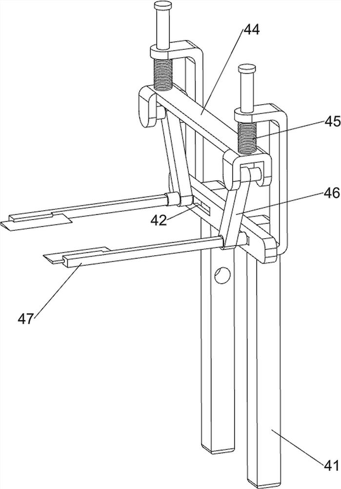
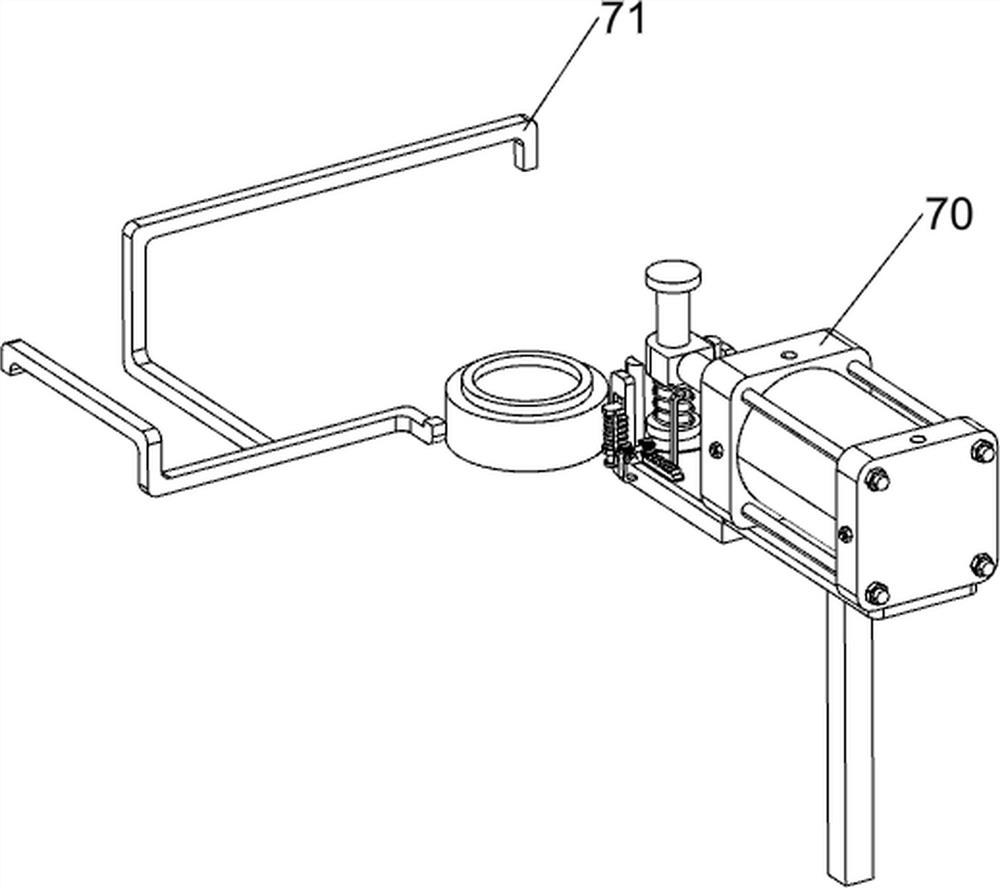
[0042] On the basis of Example 1, such as figure 1 , Figure 6 , Figure 7 , Figure 8 , Figure 9 , Figure 10 , Figure 11 , Figure 12 , Figure 13 and Figure 14 As shown, it also includes a cut-off mechanism 4, the cut-off mechanism 4 includes a first cylinder 40, a second pillar 41, a first connection block 43, a first slide block 44, a first spring 45, a second connection block 46 and a second slide Block 47, the base 1 is provided with a first cylinder 40, the base 1 is provided with a second pillar 41, the second pillar 41 is symmetrically provided with a chute 42, and the second pillar 41 is symmetrically provided with a first connecting block 43, the second pillar 41 is symmetrically provided with a first connecting block 43, A first slide block 44 is slidably connected between a connection block 43, a first spring 45 is arranged between the first slide block 44 and the first connection block 43, and a second spring 45 is arranged symmetrically on the first ...


PUM


Abstract

The invention relates to a lens production device, in particular to an automatic lens production device. According to the automatic lens production device, a stock solution can be heated and internalstress in a lens can be eliminated while discharging is conducted. The automatic lens production device comprises a base and a heating mechanism, wherein a discharging mechanism and the heating mechanism are arranged on the base. According to the automatic lens production device, the stock solution is discharged through the discharging mechanism, and then the stock solution is heated under the cooperation of the heating mechanism, so that the stock solution in the discharging mechanism can be prevented from being solidified in the discharging process of the discharging mechanism; the stock solution is automatically cut off through the arrangement of a cutting-off mechanism, so that manual cutting-off is not needed; through the arrangement of an extrusion mechanism, automatic extrusion forming of the lens is achieved, and through cooperation of the heating mechanism, internal stress in the lens can be removed.

Description

technical field [0001] The invention relates to a lens production device, in particular to an automatic lens production device. Background technique [0002] People produce lenses, most of which are made of resin, glass or optical materials. Usually, before the production, the staff needs to configure the materials required for making the lenses. After the configuration is completed, heat them to fuse them into the original solution, and then Then pour the stock solution into the device for processing and producing lenses to make the lenses. Because the lens has high viscosity and is easy to solidify, but the existing lens production equipment usually cannot realize the heating of the stock solution, so it is necessary to manually use the heater to heat the stock solution. Heating, in addition, there will be internal stress after the lens is extruded, and most of the existing devices can only realize the forming of the lens, and cannot better eliminate the internal stress in...

Claims


Application Information

Patent Timeline
IPC IPC(8): B29C39/06B29C39/24B29C39/38B29C39/36B29C39/22B29C69/00B26D1/10B26D5/12C03B19/02B29L11/00
CPCB29C39/06B29C39/24B29C39/38B29C39/36B29C39/22B29C69/001B26D1/10B26D5/12C03B19/02B29L2011/0016Y02P40/57
Inventor 马翠
Owner CHONGQING JINGCHENMEI TECH CO LTD
Why Eureka
Try Eureka