Micro light-emitting diode transfer method and display panel

A technology of micro-light-emitting diodes and transfer methods, which is applied in the direction of electrical components, electrical solid devices, circuits, etc., can solve problems such as poor yield rate and increased difficulty in picking up operations by transfer heads, so as to improve stability and consistency, and improve yield rate effect

Active Publication Date: 2021-03-30
苏州芯聚半导体有限公司
View PDF8 Cites 7 Cited by
  • Summary
  • Abstract
  • Description
  • Claims
  • Application Information

AI Technical Summary

Problems solved by technology

However, the disadvantage of this solution is that the micro-LED chips are all buried in the UV adhesive, and the pick-up of the micro-LED chips is limited by the height of the UV adhesive layer, and the difficulty of picking up multiple transfer heads of the subsequent transfer suction cup increases, resulting in poor yield

Method used


Image

  • Micro light-emitting diode transfer method and display panel
  • Micro light-emitting diode transfer method and display panel
  • Micro light-emitting diode transfer method and display panel

Examples


Embodiment Construction

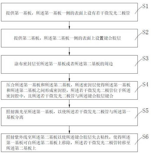
[0028] In order to make the object, technical solution and advantages of the present invention clearer, the present invention will be further described in detail below in conjunction with the embodiments and accompanying drawings. It should be understood that the specific embodiments described here are only used to explain the present invention, not to limit the present invention.

[0029] In the description of the present invention, it should be noted that the terms "center", "upper", "lower", "left", "right", "vertical", "horizontal", "inner", "outer" etc. The indicated orientation or positional relationship is based on the orientation or positional relationship shown in the drawings, and is only for the convenience of describing the present invention and simplifying the description, rather than indicating or implying that the referred device or element must have a specific orientation, or in a specific orientation. construction and operation, therefore, should not be constr...


PUM


Abstract

The invention provides a micro light-emitting diode transfer method and a display panel, and the method comprises the steps: S1, providing a first substrate, and arranging a plurality of micro light emitting diodes on the surface of one side of the first substrate; S2, providing a second substrate, wherein a bonding adhesive layer is arranged on the surface of one side of the second substrate; S2,coating a sealing layer to the periphery of the first substrate or the second substrate; S4, pressing the first substrate and the second substrate, enabling a sealing cavity to be formed between thefirst substrate and the second substrate through the sealing layer, enabling the plurality of micro light-emitting diodes to be located in the sealing cavity, and enabling the plurality of micro light-emitting diodes to be bonded with the bonding glue layer; S5, irradiating laser to the first substrate to separate the plurality of micro light emitting diodes from the first substrate; and S6, irradiating ultraviolet rays to the second substrate to enable the bonding adhesive layer to lose viscosity, so that the first substrate can be removed from the second substrate, and the plurality of microlight emitting diodes are transferred to the second substrate.

Description

technical field [0001] The invention belongs to a method for manufacturing a semiconductor device, in particular to a method for transferring a micro light emitting diode and a display panel. Background technique [0002] Currently, the display market is still dominated by liquid crystal display devices (Liquid Crystal Display, LCD) and organic light emitting diodes (Organic Light Emitting Diode, OLED). Recently, as display companies are actively participating in the OLED market, micro (Micro) LED (hereinafter referred to as "micro LED") displays are gradually becoming the next-generation display. The core raw materials of LCD and OLED displays are liquid crystal (Liquid Crystal) and organic materials, respectively, while micro-LED displays use LED chips in units of 1 micron to 100 microns (μm) as light-emitting materials. [0003] In the existing manufacturing process of micro-LED displays, the focus is on the mass transfer technology of micro-LED chips, that is, how to tr...

Claims


Application Information

Patent Timeline
Patent Type & Authority Applications(China)
IPC IPC(8): H01L33/48H01L21/67H01L27/15
CPCH01L21/67144H01L27/156H01L33/486H01L2933/0033
Inventor 韦冬李庆于波赵柯
Owner 苏州芯聚半导体有限公司
Why Eureka
Try Eureka