
Multi-axis position sensing system

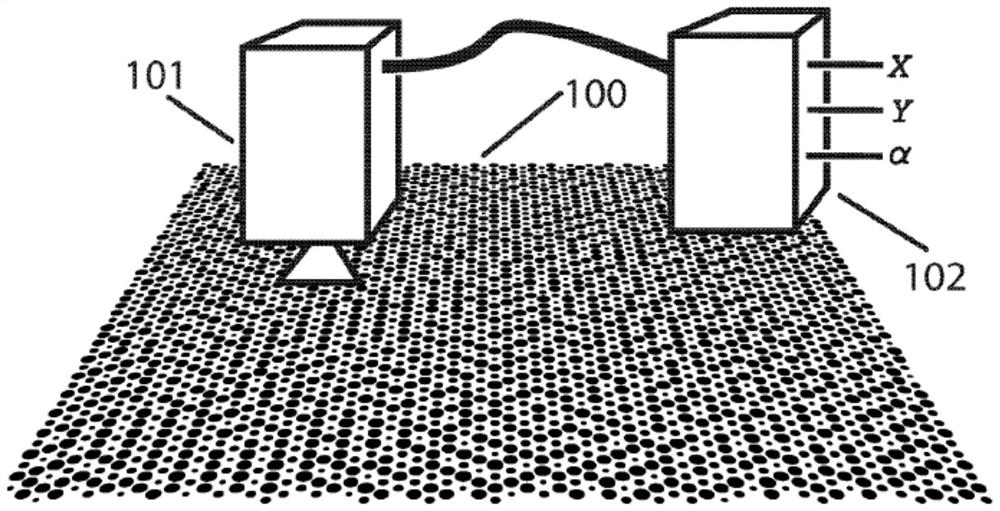
A sensing system, coding system technology, applied in the direction of sensing record carrier, data representation error detection/correction, error correction/detection using linear code, etc., to achieve the effect of high frame/sampling rate

Pending Publication Date: 2021-03-30
理查德阿拉斯
View PDF6 Cites 2 Cited by
  • Summary
  • Abstract
  • Description
  • Claims
  • Application Information

AI Technical Summary

Problems solved by technology

[0009] Given the massive data bloat behind accurate interpolation and reliability, computational efficiency and algorithmic complexity can become significant cost factors in high-speed operations

Method used


Image

  • Multi-axis position sensing system
  • Multi-axis position sensing system
  • Multi-axis position sensing system

Examples


Embodiment Construction

[0067] decoding process

[0068] exist Figure 7 A preferred embodiment of the decoding pipeline from scale 100 to position output is described in , and is now disclosed in terms of the order of the flow.

[0069] Scale symbol representation and implementation

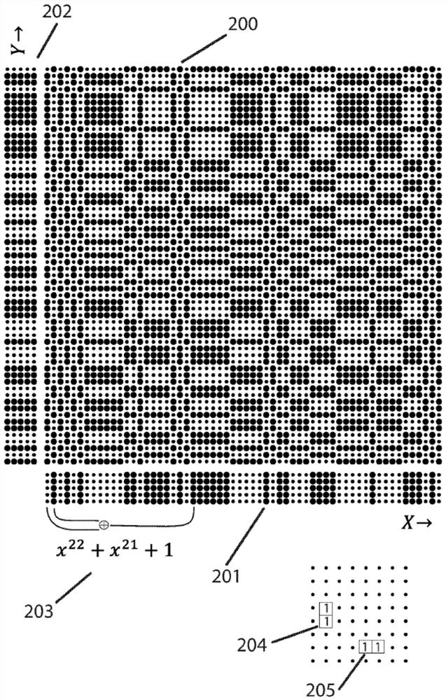
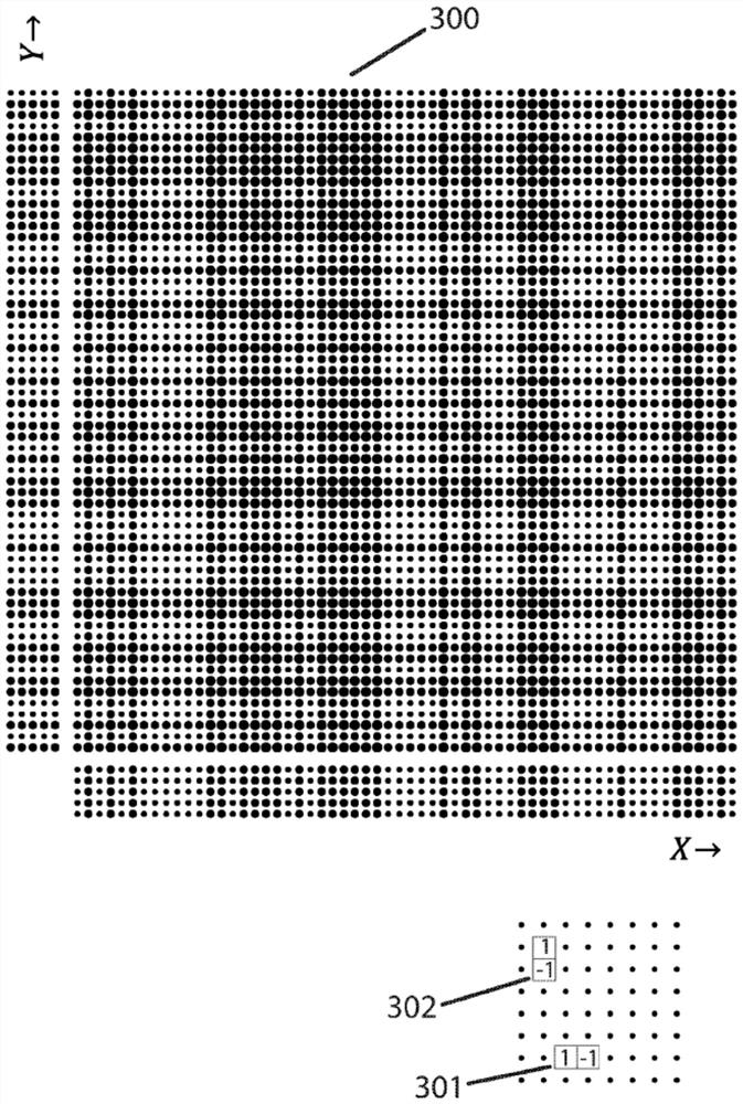
[0070] In the figures, the preferred halftone representation of a digit is depicted with a dot area proportional to the digit value. When imaging, this translates to a grayscale spread over several pixels, and later when those pixels are properly resampled and integrated, to a number that closely correlates to the original digital value. Dots have the advantage of being constant when rotated and easy to print, but it should be noted that any convenient pattern can be used, including but not limited to lines, squares, overprinted inks with subtractive overlay properties, multi-dot symbols, or full grayscale Patterns, all of the above fall within the scope of the present invention. The XOR combination produces an arr...


PUM


Abstract

Multi-axis self-location method and apparatus wherein de Bruijn sequences on 2 or more axes are convolved into an array of symbols such as halftone dots to form a reference scale. The position of an imaging device such as a camera relative to the reference scale is ascertained from the captured camera image by bit-wise reconstitution of axis position codes with simple, predominantly linear operations over small neighborhoods. Judicious choice of differential coding, LFSR generator polynomials, mathematical operators, and deconvolution kernels enables code digits of an axis to be regenerated while simultaneously cancelling out the contributions of other axes. Also optionally provided are uniform DC-balanced variants yielding greatly improved position interpolation, isometric implementationsdecodable from high-aspect-ratio sample windows, robust concatenated error correction, and extensions into n-space.

Description

technical field [0001] The present invention relates to optical position sensors that determine the position of the sensor by imaging and deciphering a portion of an encoded reference scale. Background technique [0002] The optical position sensor primarily considered here consists of two parts: a specially patterned planar reference scale and a sensor or "readhead" that moves within the scale in three degrees of freedom in x, y and arbitrary angles. A sensor, imager or camera, and an attached image processing unit can identify its position on a plane by decoding a fraction of the code patterned on the scale. Commonly referred to as "self-location," the goal is high-accuracy (nanometer), multi-axis, and rotational output measurements, which may require 100 bits in total. [0003] Self-orientation coding schemes have been studied by mathematicians for decades, and the found 2D, 4-orientation patterns (recognizable on a flat surface under any rotation) are complex to encode ...

Claims


Application Information

Patent Timeline
Patent Type & Authority Applications(China)
IPC IPC(8): G06T7/73
CPCG06T7/74G06T2207/30244G06T2207/30208G06F3/0321H03M13/15G06F3/0317G06T7/73G06F3/005G06K7/10722G06K7/1417
Inventor 理查德·阿拉斯
Owner 理查德阿拉斯
Learn More