Compaction equipment for solid waste treatment

A solid waste and equipment technology, applied in the field of compaction equipment for solid waste treatment, can solve the problems of affecting work efficiency, time-consuming and labor-consuming, and the inability to realize automatic feeding of solid waste, automatic unloading of compacted blocks, etc., to achieve convenience The effect of compressing and narrowing the gap

Inactive Publication Date: 2021-04-02
宁波阅荷思山智能科技有限公司
View PDF0 Cites 5 Cited by
  • Summary
  • Abstract
  • Description
  • Claims
  • Application Information

AI Technical Summary

Problems solved by technology

At present, the solid waste compression device is mainly a garbage compression station set up by the community. The structure is simple, and the automatic feeding of solid waste and the automatic unloading of compacted blocks cannot be realized. Manual feeding and manual unloading are required, which is time-consuming and labor-intensive. The ground affects the work efficiency and is not suitable for the use of large-scale solid waste treatment plants. In addition, due to the different sizes of solid waste and the large gaps between solid wastes, it is difficult to achieve effective treatment of solid waste without crushing the solid waste. compaction treatment

Method used


Image

  • Compaction equipment for solid waste treatment
  • Compaction equipment for solid waste treatment
  • Compaction equipment for solid waste treatment

Examples


Embodiment Construction

[0037] The present invention will be further described below in conjunction with the examples.

[0038] The following examples are used to illustrate the present invention, but cannot be used to limit the protection scope of the present invention. The conditions in the embodiment can be further adjusted according to the specific conditions, and the simple improvement of the method of the present invention under the premise of the concept of the present invention belongs to the protection scope of the present invention.

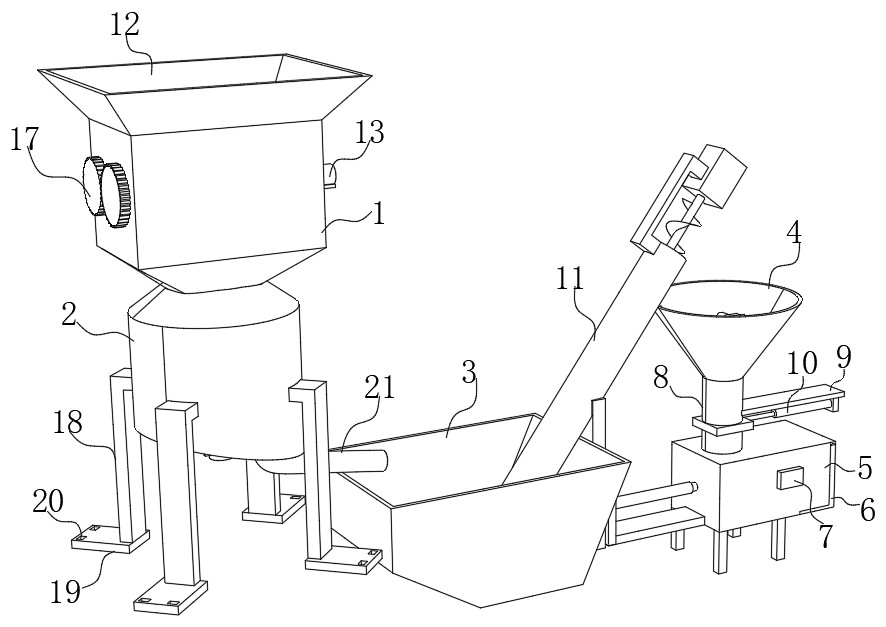
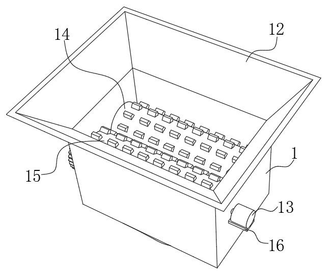
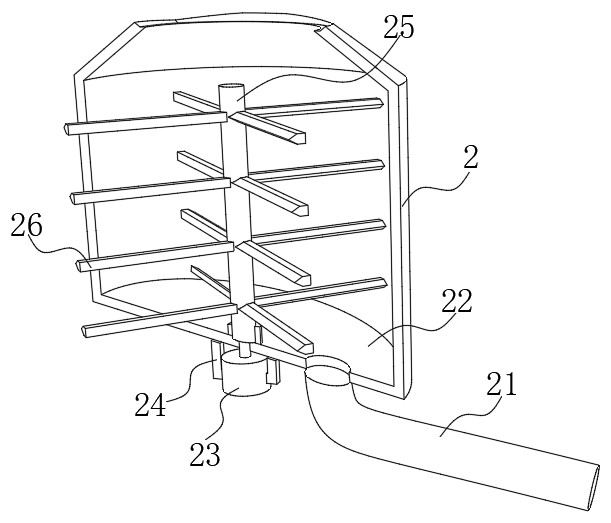
[0039] see Figure 1-11 , the present invention provides a kind of compacting equipment for solid waste treatment, comprising a crushing box 1, a storage box 3, a feed hopper 4, a feeding cylinder 11 and a compression box 5, the bottom of the crushing box 1 is fixedly connected with a crushing box 2, and the crushing box 1. The first crushing roller 14 and the second crushing roller 15 are connected in rotation. The shafts of the first crushing roller 14 and ...


PUM


Abstract

The invention discloses compaction equipment for solid waste treatment, and belongs to the technical field of waste treatment equipment. The compaction equipment comprises a crushing box, a storage box, a feeding hopper, a feeding cylinder and a compression box. The bottom of the crushing box fixedly communicates with a smashing box, a first crushing roller and a second crushing roller are rotationally connected into the crushing box, rotating shafts of the first crushing roller and the second crushing roller penetrate through the crushing box and are fixedly provided with gears, and the two gears are in engaged connection. A first motor is fixed to one side of the crushing box, an inclined bottom plate is fixed to the bottom of the crushing box, a rotating rod is rotationally connected tothe inner top face of the inclined bottom plate, and multiple cutters are fixed to the circumferential side face of the rotating rod. According to the compaction equipment for solid waste treatment,by arranging the crushing box, the smashing box, the feeding cylinder, an anti-blocking assembly, a plug plate, a discharging plate, a second electric telescopic rod and the feeding hopper, solid waste can be smashed into fine pieces in advance, the solid waste is compacted more thoroughly, continuous and stable feeding of the solid waste is achieved, and compressed waste blocks are automaticallyremoved.

Description

technical field [0001] The invention belongs to the technical field of waste treatment equipment, and in particular relates to a compacting equipment for solid waste treatment. Background technique [0002] Solid waste refers to the unavoidable generation of some solid or semi-solid waste materials that have completely or basically lost their use value in people's life and production life. The acceleration of urbanization and the rapid development of social economy have led to The amount of solid waste is increasing year by year. At present, solid waste, commonly known as garbage, is mainly disposed of by landfill and incineration: solid waste landfill occupies a large amount of land resources, and at the same time pollutes the surrounding environment and groundwater resources; while solid waste incineration produces many substances that are harmful to human health and pollutes the air. In the face of these two situations, solid waste recycling has received increasing atten...

Claims


Application Information

Patent Timeline
Patent Type & Authority Applications(China)
IPC IPC(8): B02C4/08B02C18/14B02C18/12B30B9/30B30B15/30B30B15/32
CPCB02C4/08B02C18/12B02C18/14B30B9/301B30B9/3014B30B9/3089
Inventor 龙以志
Owner 宁波阅荷思山智能科技有限公司
Why Eureka
Try Eureka