
Postoperative instrument cleaning equipment for anesthesia department

A technology for cleaning equipment and anesthesiology, which is applied in the directions of cleaning methods, cleaning methods and utensils, chemical instruments and methods using liquids, etc., which can solve problems such as troublesome and low efficiency, improve cleaning efficiency, reduce operation steps, and save time. Effect

Pending Publication Date: 2021-04-02
陈丽平
View PDF7 Cites 3 Cited by
  • Summary
  • Abstract
  • Description
  • Claims
  • Application Information

AI Technical Summary

Problems solved by technology

[0005] In order to overcome the troublesome manual cleaning of surgical instruments with sponges, and the shortcomings of low efficiency because people can only clean one surgical instrument at a time, the purpose of the present invention is to provide an anesthesia with simple operation steps and high cleaning efficiency. Scientific postoperative instrument cleaning equipment

Method used


Image

  • Postoperative instrument cleaning equipment for anesthesia department
  • Postoperative instrument cleaning equipment for anesthesia department
  • Postoperative instrument cleaning equipment for anesthesia department

Examples


Embodiment 1

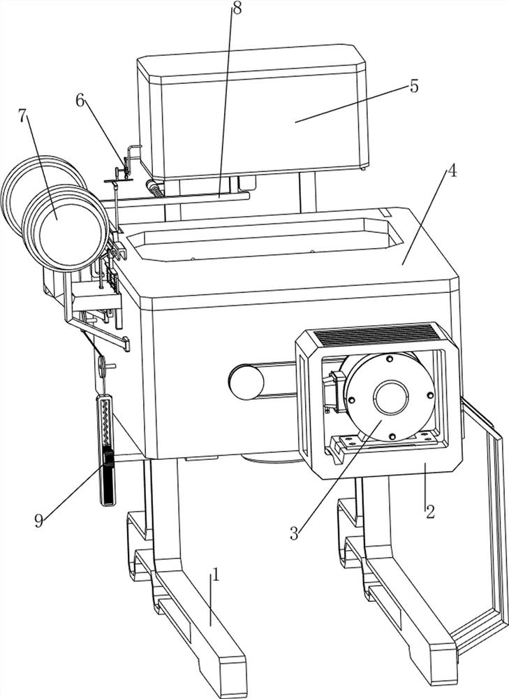
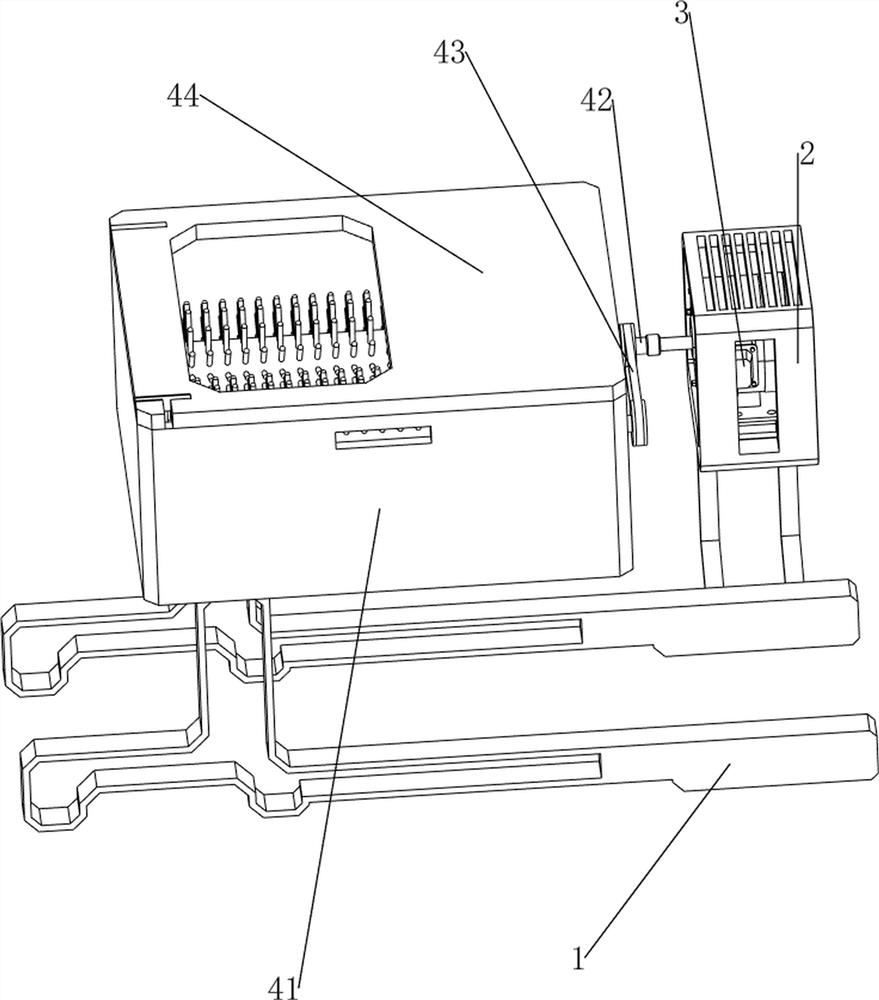
[0030] A kind of postoperative instrument cleaning equipment for anesthesiology department, such as Figure 1-3 As shown, it includes a bottom frame 1, a bracket 2, a motor 3, a flushing mechanism 4 and a steam disinfection mechanism 5, a bracket 2 is connected to the front of the right side of the bottom frame 1, a motor 3 is installed on the top of the bracket 2, and the middle of the top of the bottom frame 1 is installed. There is a flushing mechanism 4, and a steam disinfection mechanism 5 is installed on the flushing mechanism 4.

[0031] The flushing mechanism 4 includes a case 41, a cleaning assembly 42, a transmission assembly 43 and a cover plate 44. The bottom frame 1 top is connected with a case 41 in the middle, and two cleaning assemblies 42 are rotatably installed in the case 41. The cleaning assembly 42 on the right side and The output shaft of the motor 3 is connected, a transmission assembly 43 is provided between the two cleaning assemblies 42 , and a cover ...

Embodiment 2

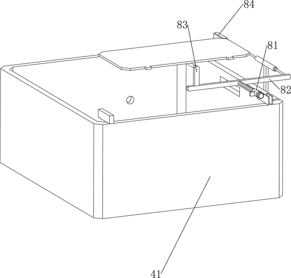
[0035] On the basis of Example 1, such as figure 1 , Figure 4 , Figure 5 , Figure 6 and Figure 7 As shown, it also includes a locking mechanism 6, and the locking mechanism 6 includes a second guide sleeve 61, an elastic clamping plate 62, a first rotating sleeve 63, a rotating plate 64, a third guiding sleeve 65 and a buoyancy long rod 66, which are sterilized The left side of the box 51 is connected with a second guide sleeve 61, the second guide sleeve 61 is provided with an elastic clamping plate 62, the elastic clamping plate 62 is in contact with the first rotating shaft 52, and the left side of the second guide sleeve 61 is connected with a first rotary sleeve 63 , the bottom of the first rotating sleeve 63 is rotatably connected with a rotating plate 64, the rotating plate 64 and the elastic clamping plate 62 are slidably matched, the upper part of the inner rear side of the box 41 is connected with a third guide sleeve 65, and the inner sliding type of the thir...


PUM


Abstract

The invention relates to cleaning equipment, in particular to postoperative instrument cleaning equipment for an anesthesia department. The postoperative instrument cleaning equipment for the anesthesia department is simple in operation step and high in cleaning efficiency. According to the technical scheme, the postoperative instrument cleaning equipment for the anesthesia department comprises abottom frame, a support, and a motor, and the support is fixedly connected to one side of the bottom frame. The motor is mounted on the support. According to the postoperative instrument cleaning equipment for the anesthesia department, through cooperation of a flushing mechanism and a steam disinfection mechanism, a large number of surgical instruments can be cleaned at a time, the cleaning efficiency is improved, the surgical instruments can be disinfected, and operation steps are reduced; and disinfectant can be injected into a box through a disinfectant mechanism to disinfect the surgicalinstruments again, so that the surgical instruments are cleaned more cleanly.

Description

technical field [0001] The invention relates to a cleaning device, in particular to a cleaning device for postoperative instruments used in anesthesiology. Background technique [0002] Surgical instruments refer to the tools used by doctors when operating on patients. They are necessary supplies in the medical industry. After the surgical instruments are used, bacteria will remain on the surface. The surgical instruments need to be cleaned to avoid bacterial infection of other patients. [0003] After the surgical instruments have been used, people generally clean the surgical instruments manually with a sponge. People soak the surgical instruments in clean water, then wipe the surgical instruments with a sponge, and clean the surgical instruments. After cleaning, they clean the surgical instruments. It is troublesome to disinfect surgical instruments, and people can only clean one surgical instrument at a time, which is inefficient. [0004] In view of the existing proble...

Claims


Application Information

Patent Timeline
IPC IPC(8): B08B3/02B08B13/00A61L2/07A61L2/18
CPCB08B3/02B08B13/00A61L2/07A61L2/18Y02A50/30
Inventor 陈丽平
Owner 陈丽平
Learn More