Steam turbine impeller production and manufacturing process

A manufacturing process and steam turbine technology, applied in the field of steam turbine impeller production and manufacturing process, can solve the problems of wasted cost, increased workload, blade shedding, etc., and achieve the effects of reducing safety risks, reducing workload and saving costs

Active Publication Date: 2021-04-02
NINGBO TIANKUN MACHINERY MFG
View PDF12 Cites 2 Cited by
  • Summary
  • Abstract
  • Description
  • Claims
  • Application Information

AI Technical Summary

Problems solved by technology

[0003] However, the following problems exist in the production and processing of steam turbine impellers at present: 1. Most of the current impellers are installed with blades one by one during production and processing, and the distance between the blades cannot be effectively adjusted, so there are errors when installing the blades, thus Requires multiple calibrations, adding unnecessary workload
[0004] 2. In the production and processing of the existing impeller, the blades and the ring frame are generally clamped and fixed. However, the clamping method is easy to cause the blades to fall off, thereby posing safety hazards and wasting costs.

Method used


Image

  • Steam turbine impeller production and manufacturing process
  • Steam turbine impeller production and manufacturing process
  • Steam turbine impeller production and manufacturing process

Examples


Embodiment Construction

[0034] In order to make the technical means, creative features, goals and effects achieved by the present invention easy to understand, the present invention will be further described below in conjunction with specific illustrations. It should be noted that, in the case of no conflict, the embodiments in the present application and the features in the embodiments can be combined with each other.

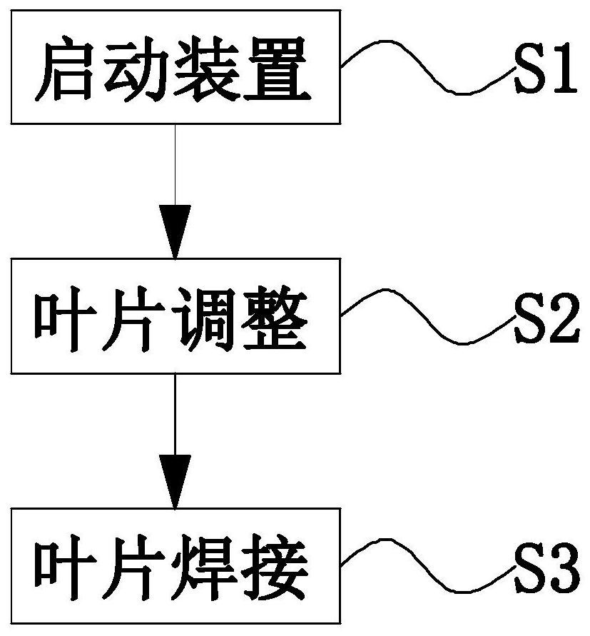
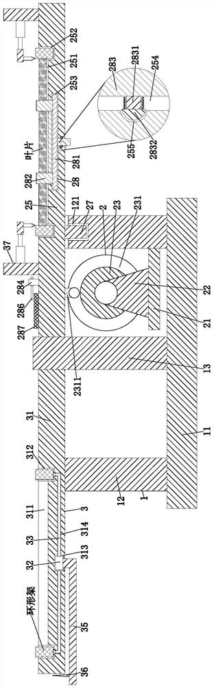
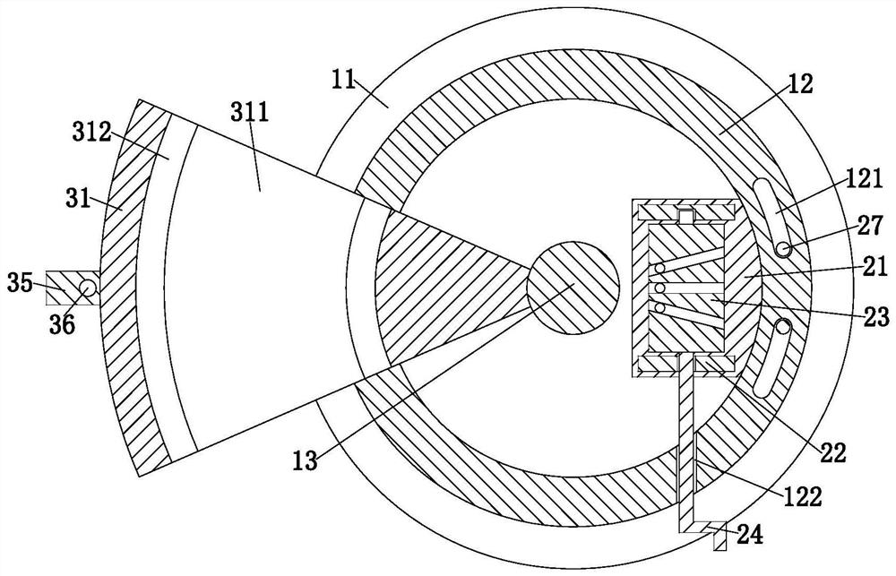
[0035] Such as Figure 1 to Figure 9 As shown, the present invention provides a steam turbine impeller manufacturing process, the steam turbine impeller manufacturing process adopts the following steam turbine impeller manufacturing device, the steam turbine impeller manufacturing device includes a base 1, an adjustment unit 2 and an execution unit 3, the base On the right side of the upper end of the seat 1, there is a linkage groove 121 arranged symmetrically front and back, the adjustment unit 2 is slidably set in the linkage groove 121, and the execution unit 3 is installed on th...


PUM


Abstract

The invention provides a steam turbine impeller production and manufacturing process. The steam turbine impeller production and manufacturing process adopts the following steam turbine impeller production and manufacturing device, the steam turbine impeller production and manufacturing device comprises a base, an adjusting unit and an executing unit, linkage grooves are formed in the right side ofthe upper end of the base in a front-and-back symmetry mode, the adjusting unit is slidably arranged in the linkage grooves, and the executing unit is installed at the upper end of the base. According to the steam turbine impeller production and manufacturing process, firstly, the problems that most of blades are mounted one by one during production and processing of an existing impeller, and thedistance between the blades cannot be effectively adjusted, so that errors exist during blade mounting, repeated calibration is needed, and unnecessary workload is increased are solved; and secondly,the problems that blades and an annular frame are generally clamped and fixed during production and machining of the existing impeller, however, due to the fact that the blades are prone to falling off in a clamping mode, potential safety hazards exist, and the cost is wasted are solved.

Description

technical field [0001] The invention relates to the technical field of production and processing of steam turbine impellers, in particular to a production and manufacturing process of steam turbine impellers. Background technique [0002] The steam turbine is a rotary steam power device. The high-temperature and high-pressure steam passes through the fixed nozzle to become an accelerated air flow and is sprayed onto the blades, so that the rotor equipped with blade rows rotates and does work externally at the same time; the steam turbine is the main equipment of a modern thermal power plant. It is also used in the metallurgical industry, chemical industry, and ship power plant. The steam turbine has the advantages of high power, high efficiency, and long life. The impeller is one of the very important parts of the steam turbine. The impeller refers to the wheel with blades. It is an integral part of the steam turbine rotor. Since the impeller plays a very important role, it ...

Claims


Application Information

Patent Timeline
Patent Type & Authority Applications(China)
IPC IPC(8): B23K31/02B23K37/00B23K37/047
CPCB23K31/02B23K37/00B23K37/047
Inventor 王鹏
Owner NINGBO TIANKUN MACHINERY MFG
Why Eureka
Try Eureka