Slotting device for manufacturing wood tooth comb
A toothed comb and rack technology, which is applied in the field of slotting devices for manufacturing wooden toothed combs, can solve the problems of low precision, time-consuming, laborious and costly, etc., and achieve the effects of reducing labor costs, eliminating manual operations, and high toothing accuracy
- Summary
- Abstract
- Description
- Claims
- Application Information
AI Technical Summary
Problems solved by technology
Method used
Image
Examples
Embodiment 1
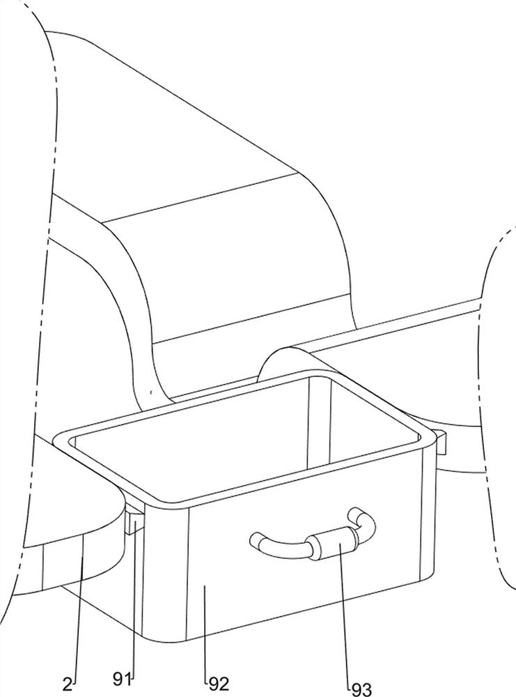
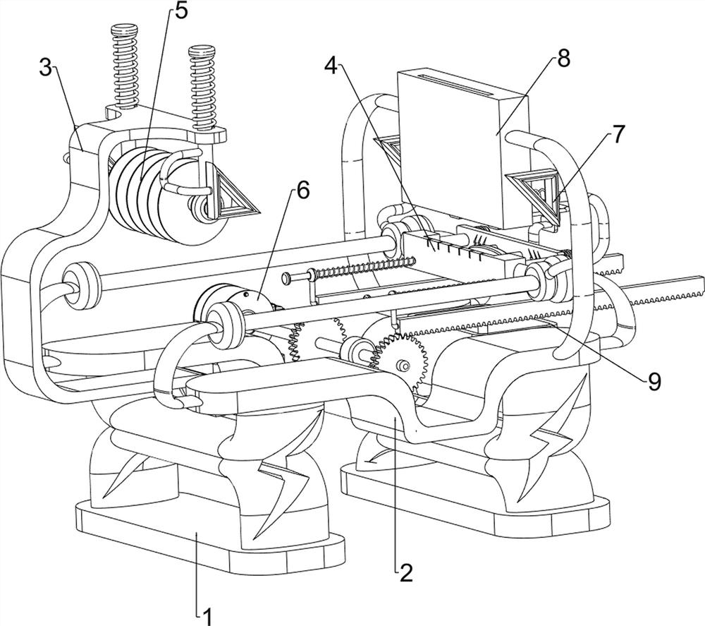
[0068] A slotting device for making wooden tooth combs, such as figure 1 , figure 2 , image 3 , Figure 4 , Figure 5 , Image 6 with Figure 7 As shown, it includes a support foot 1, a workbench 2, a first support frame 3, a fixing mechanism 4 and a cutting mechanism 5. Two workbenches 2 are connected to the top of the two support feet 1, and the middle part of the top side of the front support foot 1 A first support frame 3 is provided, a fixing mechanism 4 is provided on the workbench 2 , a cutting mechanism 5 is provided on the upper part of the first support frame 3 , and the cutting mechanism 5 cooperates with the fixing mechanism 4 .
[0069] Manual grooving has low precision, time-consuming and labor-intensive and high cost. This equipment can automatically grooving the wooden board, with high precision, time-saving and labor-saving and low cost. First, people make the 4 parts of the fixing mechanism operate, and then put the wooden board In the fixing mechanism ...
Embodiment 2
[0071] On the basis of Example 1, such as figure 2 , image 3 , Figure 5 with Image 6 As shown, the fixing mechanism 4 includes a first guide rod 41, a bracket 42, a pressing block 43 and a first spring 44, and the first guide rod 41 is connected between the front and rear sides of the workbench 2 on the left and right sides. The first guide rod 41 on the side is slidably connected with a bracket 42, the bracket 42 is slidably provided with a pressure block 43, the bracket 42 is wound with two first springs 44, and the front side of the first spring 44 is connected to the pressure block. 43, and the rear side of the first spring 44 is connected with the bracket 42.
[0072] People manually make the pressing block 43 slide backwards on the supporting block 42, and the first spring 44 changes from the initial state to a compressed state, and then the plank is placed in the supporting block 42, and then people release the pressing block 43, and the first spring 44 remains ...
Embodiment 3
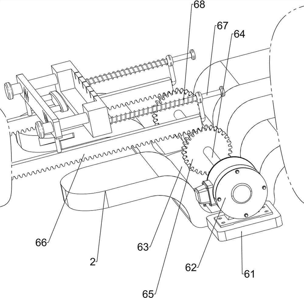
[0076] On the basis of Example 2, such as figure 1 , Figure 4 , Figure 5 , Image 6 with Figure 7 As shown, a rotating mechanism 6 is also included. The workbench 2 is provided with a rotating mechanism 6. The rotating mechanism 6 is connected with the pressing block 43. The rotating mechanism 6 includes a second support frame 61, a motor 62, a third support frame 63, a rotating shaft 64, gear 65, tooth bar 66, the 3rd guide bar 67 and the 3rd spring 68, the workbench 2 left middle part on the left side is provided with the second support frame 61, and the second support frame 61 top is equipped with motor 62, left and right sides A third support frame 63 is connected between the workbenches 2 on the side, the output shaft of the motor 62 is connected with the upper part of the third support frame 63 with a rotating shaft 64, and the rotating shaft 64 is rotationally connected with the third support frame 63, and the left and right sides of the rotating shaft 64 are A g...
PUM
 Abstract
Description
Claims
Application Information
 - R&D
- Intellectual Property
- Life Sciences
- Materials
- Tech Scout
- Unparalleled Data Quality
- Higher Quality Content
- 60% Fewer Hallucinations
Browse by: Latest US Patents, China's latest patents, Technical Efficacy Thesaurus, Application Domain, Technology Topic, Popular Technical Reports.
© 2025 PatSnap. All rights reserved.Legal|Privacy policy|Modern Slavery Act Transparency Statement|Sitemap|About US| Contact US: help@patsnap.com


