
Liquid outlet massager

The technology of a massager and a liquid outlet hole is applied in the field of liquid outlet massager, which can solve the problems of poor body feeling, high cost of tooth structure and high cost, and achieve the effects of low processing technology requirements, reduced production cost and simple structure

Pending Publication Date: 2021-04-02
深圳市景美瑞科技股份有限公司
View PDF0 Cites 0 Cited by
  • Summary
  • Abstract
  • Description
  • Claims
  • Application Information

AI Technical Summary

Problems solved by technology

[0002] With the gradual improvement of people's life, more and more people pay attention to personal health care, such as: head massage plays an important role in promoting the blood circulation of the head. Massage, however, most of the existing massage brushes only have a separate massage function, the function is too single, and a small part of the massage brush with the liquid discharge function is mostly made of hardware or the liquid is discharged through the pump.
[0003] Hardware materials generally discharge liquid through elastic balls, and its structure is complex. It requires the perfect cooperation of teeth, springs, and balls to realize liquid discharge when massaging the skin and prevent liquid dripping when not massaging. This requires high machining accuracy for the teeth. Therefore, this Tooth-like structure costs more
Moreover, the method of rolling out the liquid is easy to pinch the user's hair when massaging the scalp, and the hardware material is high in hardness, which makes the body feel poor when massaging
The other type of massage brush needs to use a pump to make the liquid out of the teeth. It needs to use electronic devices, and the body needs to be waterproofed. Its structure is complicated and the cost is high.

Method used


Image

  • Liquid outlet massager
  • Liquid outlet massager
  • Liquid outlet massager

Examples


Embodiment Construction

[0029] In order to make the object, technical solution and advantages of the present invention clearer, the present invention will be further described in detail below in conjunction with the accompanying drawings and embodiments. It should be understood that the specific embodiments described here are only used to explain the present invention, not to limit the present invention.

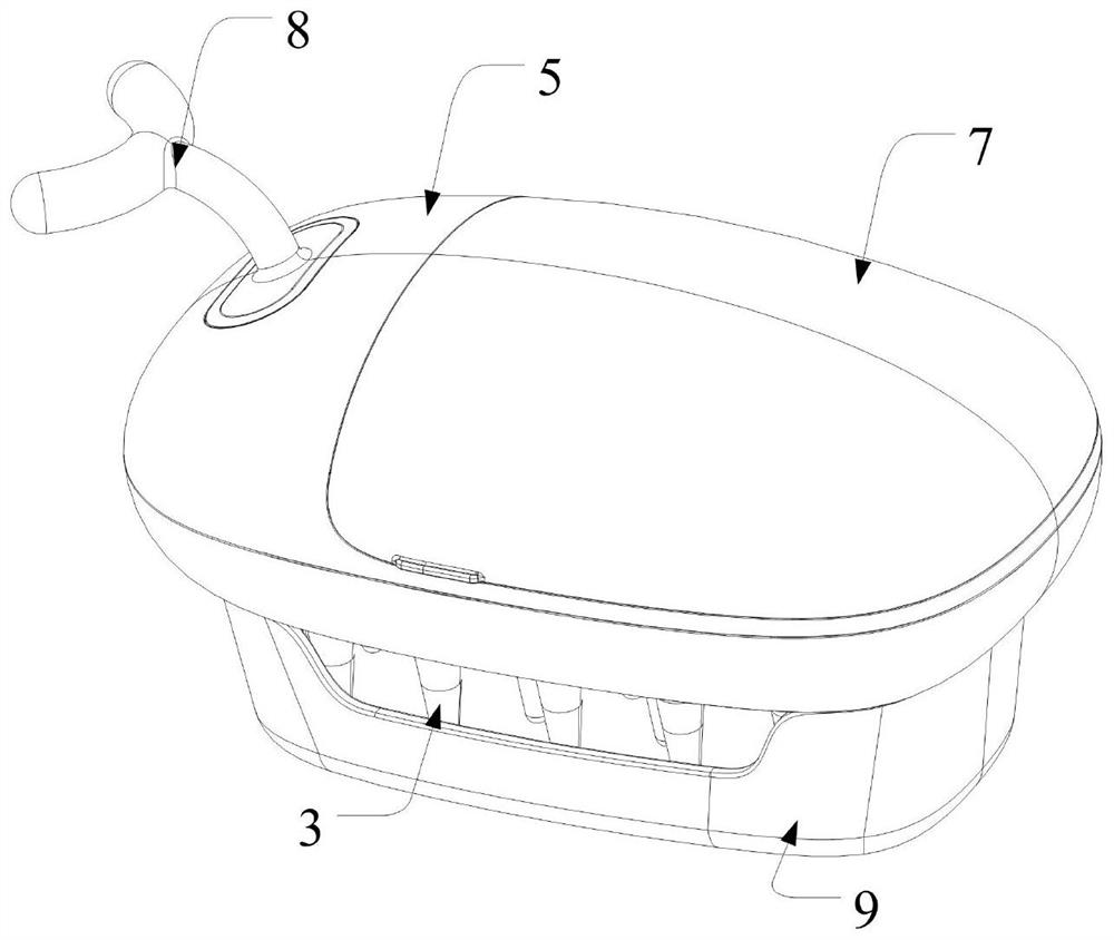
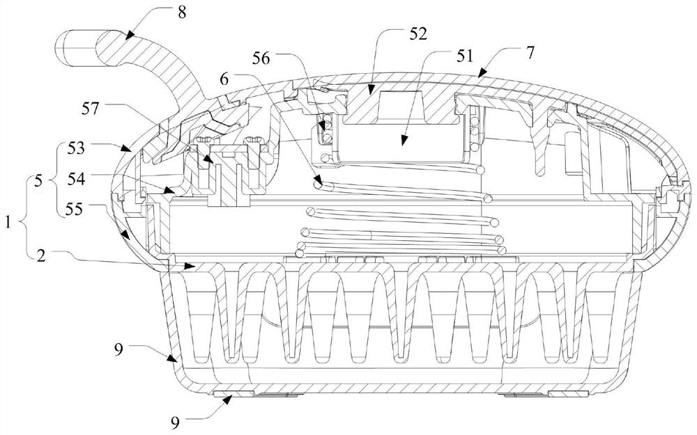
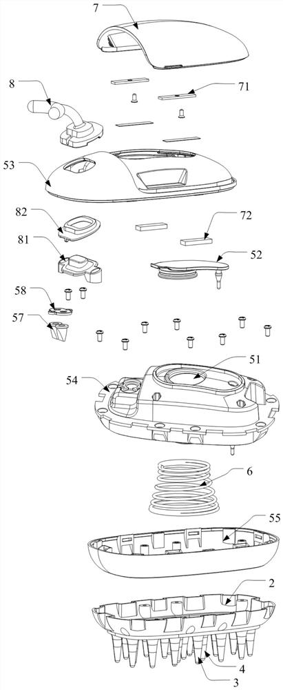
[0030] see figure 1 , figure 2 , image 3 and Figure 4 , the liquid massager provided by the present invention includes a liquid storage assembly 1 and a tooth plate 2, and the tooth plate 2 is connected with the liquid storage assembly 1 to form at least one liquid storage chamber (not shown in the figure), and the tooth plate 2 is provided with a number of liquid outlet teeth 3, the liquid outlet teeth 3 are soft teeth, the tip of the liquid outlet teeth 3 has at least one liquid outlet hole 31, which communicates with the liquid storage chamber, and the liquid outlet teeth 3 are subjected t...


PUM


Abstract

The invention discloses a liquid outlet massager which comprises a liquid storage assembly and a toothed plate. The toothed plate is connected with the liquid storage assembly to form at least one liquid storage cavity, a plurality of liquid outlet teeth are arranged on the toothed plate and are soft teeth, at least one liquid outlet hole is formed in the tips of each liquid outlet tooth and communicated with the liquid storage cavity, and after the liquid outlet teeth are pressed, liquid can be discharged from the liquid outlet holes. By slightly pressing the liquid outlet massager, the heads(namely the tips) of the liquid outlet teeth make contact with the skin, the liquid outlet teeth deform through external force in the massage process to enable the internal pressure intensity to be smaller than the atmospheric pressure to discharge liquid, the massage effect can be achieved while care liquid is guided out, and when the soft tooth structures are used for massaging by contact, thephenomena of pain, hair pinching or skin scratching are avoided. Compared with an existing high-hardness hardware liquid outlet massager or a liquid outlet massager needing pump pressure, the liquid outlet massager has the advantages of being smooth in liquid outlet, high in comfort level, simple in structure, low in machining process requirement and the like, and the production cost is effectively reduced.

Description

technical field [0001] The invention relates to the technical field of nursing appliances, in particular to a liquid outlet massager. Background technique [0002] With the gradual improvement of people's life, more and more people pay attention to personal health care, such as: head massage plays an important role in promoting the blood circulation of the head. Massage, however, most of the existing massage brushes only have a separate massage function, the function is too single, and a small number of massage brushes with a liquid outlet function are mostly made of hardware or use a pump to discharge the liquid. [0003] Hardware materials generally discharge liquid through elastic balls, and its structure is complex. It requires the perfect cooperation of teeth, springs, and balls to realize liquid discharge when massaging the skin and prevent liquid dripping when not massaging. This requires high machining accuracy for the teeth. Therefore, this Tooth-like structures ar...

Claims


Application Information

Patent Timeline
Patent Type & Authority Applications(China)
IPC IPC(8): B65D47/42
CPCB65D47/42A61H2201/0153A61H2201/105A61H2201/0173A61H9/0028A61H11/00A61H2201/5051A61H2201/169A61H2201/1253A61H2201/1669A61H2205/021A61H2201/1695
Inventor 龚震王浩谭小琳田传伟
Owner 深圳市景美瑞科技股份有限公司
Learn More