Equipment hoisting structure

A kind of equipment and hoisting technology, applied in hoisting devices, portable lifting devices, etc., can solve problems such as low efficiency, difficulty, and difficult operation, and achieve the effects of convenient operation, portability, and easy disassembly

Active Publication Date: 2021-04-02
NANJING HUASHI ELECTRONICS SCI
View PDF5 Cites 2 Cited by
  • Summary
  • Abstract
  • Description
  • Claims
  • Application Information

AI Technical Summary

Problems solved by technology

[0002] Power electronic equipment such as high-power power supplies, frequency converters, traction converters, and auxiliary converters are mainly suitable for indoor layouts (generally referring to power distribution rooms, laboratories, substations, etc.), as well as other application environments, such as inside railway locomotives, etc. , and no matter what environment it is installed in, its core power module equipment is currently relatively heavy, and its own weight generally reaches 30-50kg. When the operating space is limited, it can pass 2 to 3 It is unreasonable and safe for people to manually dismantle and install
[0003] In the indoor layout environment, since the layout interval of the front and rear cabinets is generally within the range of 1.2-2 meters, when the space layout is limited, the modules can only be disassembled and assembled manually when maintaining the modules. However, according to the installation position and arrangement of the modules, there are some arranged up and down, left and right, some are arranged in the middle, and some are arranged above. No matter what the arrangement is, when a single module is too heavy, relying on manpower (2- 3 people) there are certain risks, and produce low-efficiency operation process
[0004] In the field of rail transit, the traction and auxiliary converter cabinets are generally installed inside the locomotive carriages. The gap between the top of the cabinet and the interior roof of the carriages is small, and the operating space is more compact and comfortable compared to the indoor layout on the ground. In this case, it is more difficult and difficult to maintain the modules in the traction or auxiliary converter cabinet

Method used


Image

  • Equipment hoisting structure
  • Equipment hoisting structure
  • Equipment hoisting structure

Examples


Embodiment Construction

[0085] In order to make the object, technical solution and advantages of the present invention more clear, the present invention will be further described in detail below in conjunction with the examples. It should be understood that the specific embodiments described here are only used to explain the present invention, not to limit the present invention.

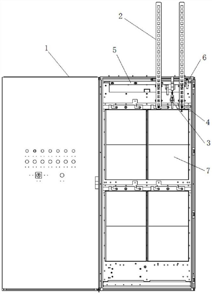
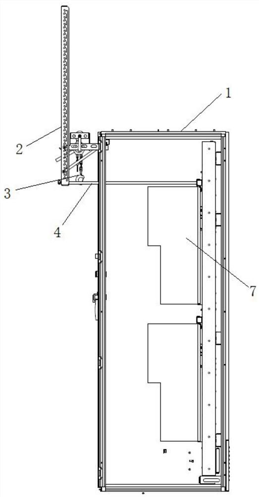
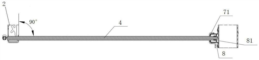
[0086] combine Figure 1-3 , an equipment hoisting structure, including a cabinet 1 for installing equipment 7, two groups of movable column assemblies 2, equipment lifting devices 3, two sliding rod assemblies 4, top clamping seats 5, hanging Rod assembly 6, the top clamping seat 5 is installed on the top of the cabinet 1, the movable column assembly 2 is installed on the top clamping seat 5, and the hanging rod assembly 6 is installed on the movable column assembly 2 One end of the equipment lifting device 3 is installed and connected with the hanging rod assembly 6, and the other end can be connected with the equipment ...


PUM


Abstract

The invention discloses an equipment hoisting structure. The equipment hoisting structure comprises a cabinet used for installing equipment, two sets of movable stand column assemblies, an equipment lifting device, two sliding rod assemblies, a top clamping base and a hanging rod assembly are arranged on the cabinet, the top clamping base is installed at the top of the cabinet, the movable stand column assemblies are installed on the top clamping base, the hanging rod assembly is installed on the movable stand column assemblies, one end of the equipment lifting device is connected with the hanging rod assembly, the other end of the equipment lifting device can be connected with the equipment to realize lifting of the equipment, the front ends of the sliding rod assemblies penetrate throughthe movable stand column assemblies, the rear ends of the sliding rod assemblies are fixed in the cabinet, and two L-shaped clamping notches are formed in an equipment hanging frame on the equipment.The structure is simple in structural form, high in expandability and adjustability, and light in weight, is portable, safe, reliable, and is capable of being operated by a single person and installed without auxiliary tools such as a sleeve and a wrench, and rapid disassembly and assembly are realized by adopting the clamping type installation concept.

Description

technical field [0001] The invention belongs to the technical field of equipment installation, in particular to an equipment hoisting structure. Background technique [0002] Power electronic equipment such as high-power power supplies, frequency converters, traction converters, and auxiliary converters are mainly suitable for indoor layouts (generally referring to power distribution rooms, laboratories, substations, etc.), as well as other application environments, such as inside railway locomotives, etc. , and no matter what environment it is installed in, its core power module equipment is currently relatively heavy, and its own weight generally reaches 30-50kg. When the operating space is limited, it can pass 2 to 3 It is not reasonable and safe for people to carry out manual dismantling and installation. [0003] In the indoor layout environment, since the layout interval of the front and rear cabinets is generally within the range of 1.2-2 meters, when the space layou...

Claims


Application Information

Patent Timeline
Patent Type & Authority Applications(China)
IPC IPC(8): B66D3/00B66D3/12
CPCB66D3/00B66D3/12
Inventor 宫启杰陈爱林
Owner NANJING HUASHI ELECTRONICS SCI
Why Eureka
Try Eureka