
Concrete-filled steel tube arch bridge transverse support structure, arch bridge and transverse support structure design method

A technology of steel tube concrete and design method, which is applied in the direction of arch bridge, bridge construction, design optimization/simulation, etc. It can solve problems affecting the permeability of pedestrians and traffic, difficulties in high-altitude installation operations, and dense arrangement of cross braces, etc., to improve technical economy Sexuality, shortening the construction period, and improving construction efficiency

Pending Publication Date: 2021-04-02
SICHUAN VOCATIONAL & TECHN COLLEGE OF COMM
View PDF0 Cites 0 Cited by
  • Summary
  • Abstract
  • Description
  • Claims
  • Application Information

AI Technical Summary

Problems solved by technology

[0005] The object of the present invention is to aim at the symmetrical arrangement of the upper and lower plane cross braces of the existing concrete-filled steel tube arch bridge existing in the prior art, which not only consumes a large amount of materials, but also requires high-altitude installation due to the excessive number of upper and lower plane cross braces of the main arch. The operation is very difficult, and the arrangement of cross braces is too dense, which will also affect the permeability of pedestrians and traffic. Provide a design method for the cross brace structure of the steel tube concrete arch bridge, the arch bridge and the cross brace structure

Method used


Image

  • Concrete-filled steel tube arch bridge transverse support structure, arch bridge and transverse support structure design method
  • Concrete-filled steel tube arch bridge transverse support structure, arch bridge and transverse support structure design method
  • Concrete-filled steel tube arch bridge transverse support structure, arch bridge and transverse support structure design method

Examples


Embodiment

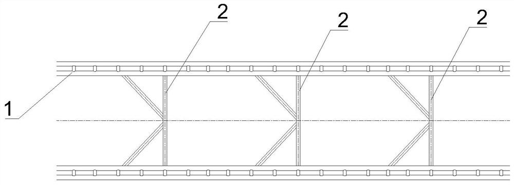
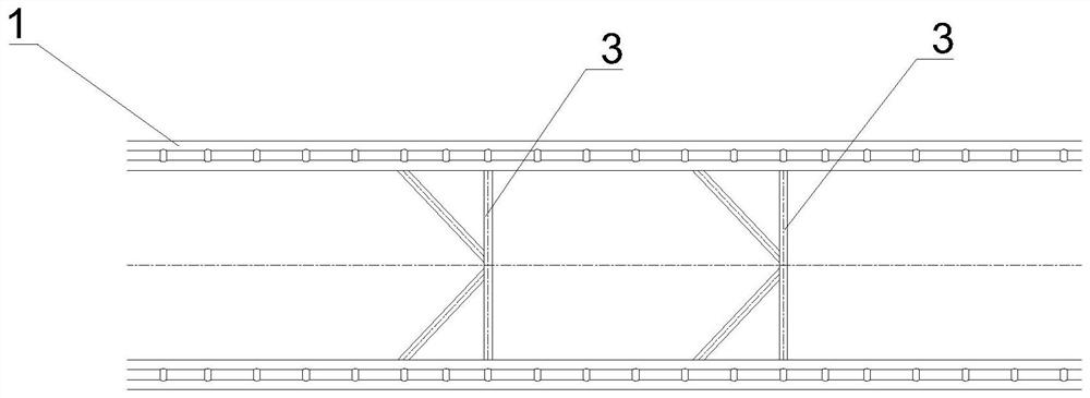
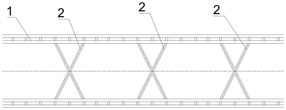
[0053] Such as Figure 1-Figure 5 As shown, this embodiment provides a steel tube concrete arch bridge cross brace structure, including an upper cross brace assembly 2 and a lower cross brace assembly 3;

[0054] The upper cross brace assembly 2 is used to be arranged on the upper plane of the main arch 1, and the lower cross brace assembly 3 is used to be arranged on the lower plane of the main arch 1;

[0055] The number of the upper cross brace assembly 2 and the lower cross brace assembly 3 are different, specifically, the number of the lower cross brace assembly 3 is less than the number of the upper cross brace assembly 2 .

[0056]The upper cross brace assembly 2 and the lower cross brace assembly 3 are misplaced, specifically, the number difference between the upper cross brace assembly 2 and the lower cross brace assembly 3 is 1-3.

[0057] The distance between adjacent upper cross brace assemblies 2 is the first distance, the distance between adjacent lower cross br...


PUM


Abstract

The invention discloses a concrete-filled steel tube arch bridge transverse support structure, an arch bridge and a transverse support structure design method. The transverse support structure comprises an upper transverse support assembly and a lower transverse support assembly. The upper transverse support assembly is used for being arranged on the upper plane of a main arch, and the lower transverse support assembly is used for being arranged on the lower plane of the main arch. The number of the upper transverse supporting assemblies is larger than that of the lower transverse supporting assemblies, and the upper transverse supporting assemblies and the lower transverse supporting assemblies are arranged in a staggered mode. According to the concrete-filled steel tube arch bridge crossarm structure, the number of the upper cross arm assemblies is larger than that of the lower cross arm assemblies, the upper cross arm assemblies and the lower cross arm assemblies are arranged in astaggered mode, transverse space connection of a main arch is tighter, and the number of the lower cross arm assemblies of the main arch is reduced; meanwhile, the transverse stability of the main arch and the technical economy of the overall transverse support design of the arch bridge are improved, the construction cost can be reduced while the bearing safety and stability of the arch bridge areguaranteed, the construction risk caused by the large number of the lower transverse support assemblies can be reduced, and the construction efficiency is improved.

Description

technical field [0001] The invention relates to the field of bridges, in particular to a steel tube concrete arch bridge cross brace structure, an arch bridge and a design method for the cross brace structure. Background technique [0002] As a kind of excellent steel-concrete composite structure bridge, concrete-filled steel tube arch bridge has been developed rapidly in recent years. The number of concrete-filled steel tube concrete arch bridges is increasing, and the span is getting larger and larger. Reasonable main arch cross brace structure can improve the overall stiffness and stability of the bridge. It can also improve the dynamic performance of the bridge. [0003] Existing concrete-filled steel tube arch bridges generally have X-shaped cross-stays, K-shaped cross-stays, I-shaped cross-stays and rice-shaped cross-stays in the form of cross-braces, and the cross-braces are arranged symmetrically on the upper and lower planes of the main arch. According to the resea...

Claims


Application Information

Patent Timeline
IPC IPC(8): E01D4/00G06F30/13G06F30/23G06F119/14
CPCE01D4/00E01D2101/268G06F30/13G06F30/23G06F2119/14
Inventor 赵艺程牟廷敏范碧琨倪春梅梁健李胜许诺孙才志邹圻李成君范翊杜凤何易修李畅何娇阳
Owner SICHUAN VOCATIONAL & TECHN COLLEGE OF COMM
Learn More