Cabinet door capable of being automatically controlled to be closed for smart home

A smart home and cabinet door technology, which is applied to wardrobes, cabinets, furniture parts, etc., can solve the problems of increased force required to open the door, moldy and hairy clothes inside, and loose opening of the frame door, so as to promote air flow and hand feeling. Excellent, anti-mold effect

Inactive Publication Date: 2021-04-02
闫志伟
View PDF1 Cites 0 Cited by
  • Summary
  • Abstract
  • Description
  • Claims
  • Application Information

AI Technical Summary

Problems solved by technology

[0005] The purpose of the present invention is to provide a cabinet door that can be automatically controlled and closed by a smart home to solve the problem that after the cabinet door is closed in the above background technology, the air inside the sealed cabinet cannot circulate. In the south or some coastal areas, the sealed cabinet door It is easy to cause the internal moisture to increase continuously, resulting in mildew and hair growth on the internal clothes. The existing cabinet doors mostly control the angle of the cabinet door by increasing friction, which leads to an increase in the force required to open the door. Later, the frame door is worn and opened very loosely. And after the cabinet door is opened, it is easy to forget to close it, and the obsessive-compulsive disorder will return to check repeatedly

Method used


Image

  • Cabinet door capable of being automatically controlled to be closed for smart home
  • Cabinet door capable of being automatically controlled to be closed for smart home
  • Cabinet door capable of being automatically controlled to be closed for smart home

Examples


Embodiment Construction

[0026] The following will clearly and completely describe the technical solutions in the embodiments of the present invention with reference to the accompanying drawings in the embodiments of the present invention. Obviously, the described embodiments are only some, not all, embodiments of the present invention.

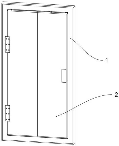
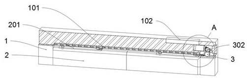
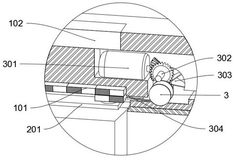
[0027] see Figure 1 to Figure 7 , an embodiment provided by the present invention: a smart home can automatically control the closed cabinet door, including a door frame 1; the door frame 1 includes a magnetic strip 101, a control module 102, a ventilation pipe 103, a filter block 104, an air outlet 105 and Fan 106, a control module 102 is fixedly connected to the top of the door frame 1; a ventilation pipe 103 is provided in the middle of the door frame 1; a fan 4 is fixed at the bottom of the ventilation pipe 103, and fan blades are arranged on the outside of the fan 4, and the fan 4 is connected to the ventilation hole on the back of the door frame 1 Connected, t...


PUM


Abstract

The invention discloses a cabinet door capable of being automatically controlled to be closed for a smart home, and relates to the technical field of smart homes. The problem that a frame door is abraded and opened very loosely in the later period is solved. The cabinet door capable of being automatically controlled to be closed for the smart home comprises a door frame, wherein the door frame comprises a magnetic strip, a control module, a ventilation pipe, a filter block, an air outlet and an air outlet fan; the top of the door frame is fixedly connected with the control module; the ventilation pipe is arranged in the middle of the door frame; the middle of the ventilation pipe is fixedly connected with the filter block; a moisture absorption medium is arranged in the filter block; the outer side of the air outlet is rotationally connected with an air guide strip; the outer side of the air outlet fan is rotationally connected with an air guide ring; and the bottom of the ventilationpipe is fixedly connected with a draught fan. According to the cabinet door, through multiple magnetic blocks with positive electrodes and negative electrodes connected with one another in the magnetic strip, the cabinet door can be opened and fixed at multiple angles, the situation that the cabinet door is loosened due to later friction consumption is avoided, and the use durability of the cabinet door is enhanced.

Description

technical field [0001] The invention relates to the technical field of smart home, in particular to a cabinet door which can be automatically controlled and closed by smart home. Background technique [0002] Smart home is based on the residence as a platform, using integrated wiring technology, network communication technology, security technology, automatic control technology, audio and video technology to integrate the facilities related to home life, to build an efficient management system for residential facilities and family schedules, and to improve Home safety, convenience, comfort, artistry, and to achieve an environmentally friendly and energy-saving living environment. [0003] For example, the patent No. is CN109907516A, which discloses a wardrobe, particularly a smart home wardrobe. A smart home wardrobe, including a wardrobe body, a cabinet door, a clothes shaft, a clothes hanger, an upper partition, a lower partition, a control link, a vertical shaft, a push-...

Claims


Application Information

Patent Timeline
IPC IPC(8): E05F15/605A47B97/00A47B61/00B01D53/26
CPCA47B61/00A47B97/00B01D53/261E05F15/605
Inventor 闫志伟
Owner 闫志伟
Why Eureka
Try Eureka