Fairing and pressure reducing valve

A technology of fairing and pressure reducing valve, which is applied in the direction of balance valve, valve device, valve details, etc., can solve the problems affecting the health of the staff, the technical water supply flow of the unit is large, and the operation noise is large, so as to improve the effect of voltage stabilization, Effect of reducing fluid noise and noise reduction

Active Publication Date: 2021-04-02
TIANSHENGQIAO TWO HYDROPOWER CO LTD +2
View PDF6 Cites 0 Cited by
  • Summary
  • Abstract
  • Description
  • Claims
  • Application Information

AI Technical Summary

Problems solved by technology

In the actual use process, it was found that when the inlet pressure of the above-mentioned pressure reducing valve is high, due to the large pressure reduction ratio and the large technical water supply flow rate of the unit, the above-mentioned pressure reducing valve has no special noise reduction design, and there is a problem of high operating noise. The maximum noise value of the above-mentioned pressure reducing valve is more than 100 decibels, which seriously affects the health of on-site workers

Method used


Image

  • Fairing and pressure reducing valve
  • Fairing and pressure reducing valve
  • Fairing and pressure reducing valve

Examples


Embodiment 1

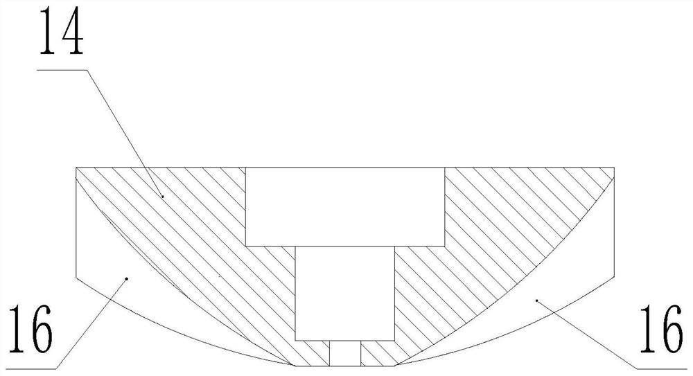
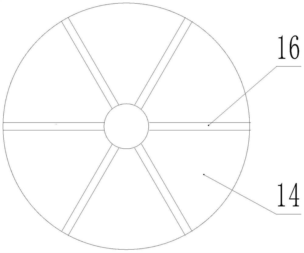
[0027] like figure 1 and figure 2 A kind of fairing shown, comprises the cover body 14 that is conical shape, and the outside wall of cover body 14 is the conical surface that diameter is big up and down is small, and the outside wall of cover body 14 is the curved surface that protrudes outwards, and cover body 14 A plurality of splitter plates 16 are connected on the outer side wall of the cover body 14, and the plurality of splitter plates 16 are arranged at intervals along the circumferential direction of the cover body 14, and the plurality of splitter plates 16 are arranged perpendicular to the circumferential direction of the cover body 14.

[0028] In this embodiment, a plurality of splitter plates 16 are arranged at equal intervals along the circumferential direction of the cover body 14 .

[0029] In this embodiment, the upper edge of the splitter plate 16 is connected to the outer side wall of the cover body 14 , and the lower edge of the splitter plate 16 is a cu...

Embodiment 2

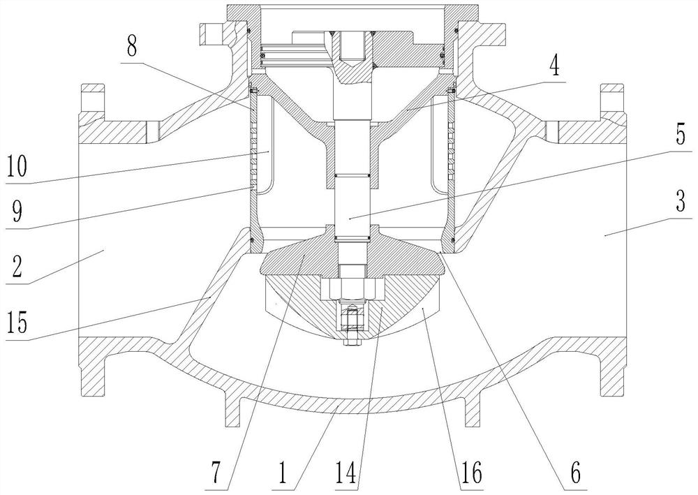
[0033] like Figure 3 to Figure 5 The pressure reducing valve shown includes a valve body 1 provided with a medium inlet channel 2 and a medium outflow channel 3. A partition 15 is provided inside the valve body 1, and a communication medium inlet channel 2 and a medium outflow channel are provided on the partition 15. The valve port 6 of the channel 3, the valve body 1 is also provided with a valve stem 5 and a throttling cone 7 installed on the lower end of the valve stem 5. The throttling cone 7 can adjust the opening of the valve port 6. The upper end of the valve stem 5 is usually There is a piston matched with the cylinder liner 4, the lower side of the throttle cone 7 is connected with the fairing described in the first embodiment, the lower end of the valve stem 5 passes through the throttle cone 7 and the fairing, and the valve stem 5 is provided with Pressing down against the step surface of the throttle cone 7, a nut is connected to the lower end of the valve stem 5...

Embodiment 3

[0042] like Image 6 and Figure 7 In the pressure reducing valve shown, the difference between the noise reduction sleeve 8 in this embodiment and the noise reduction sleeve 8 described in Embodiment 1 lies in the arrangement of multiple guide parts. In this embodiment, A plurality of deflectors constitute a plurality of second deflectors 11 extending in the vertical direction and a plurality of third deflectors 12 extending in the vertical direction, and each second deflector 11 is composed of at least two deflectors. connected sequentially, multiple second deflectors 11 are arranged at intervals along the circumference of the noise reduction sleeve 8, each third deflector 12 is formed by connecting at least two deflectors in sequence, and multiple third deflectors The deflectors 12 are arranged at intervals along the circumference of the noise reduction sleeve 8, and the plurality of second deflectors 11 are located on the upper side of the plurality of third deflectors 12...


PUM


Abstract

The invention relates to a fairing and a pressure reducing valve. The fairing comprises a conical fairing body, wherein the outer side wall of the fairing body is a conical surface with the diameter being large in the upper part and small in the lower part; the outer side wall of the fairing body is a curved surface protruding outwards; multiple splitter plates are connected onto the outer side wall of the fairing body, and are arranged in the circumferential direction of the fairing body at intervals; the multiple splitter plates are all perpendicular to the circumferential direction of the fairing body; and the fairing is arranged in the pressure reducing valve. According to the fairing and the pressure reducing valve provided by the invention, noise generated in the operation process ofthe pressure reducing valve can be reduced.

Description

technical field [0001] The invention relates to a valve, in particular to a fairing cover and a pressure reducing valve. Background technique [0002] For example, the Chinese patent with the application number CN201410555665.9 discloses a piston type pressure reducing valve, and the pressure reducing valve of this structure is often used in the water supply system of hydropower station technology. In the actual use process, it was found that when the inlet pressure of the above-mentioned pressure reducing valve is high, due to the large pressure reduction ratio and the large technical water supply flow rate of the unit, the above-mentioned pressure reducing valve has no special noise reduction design, and there is a problem of high operating noise. The noise value of the maximum operation of the above-mentioned pressure reducing valve reaches more than 100 decibels, which seriously affects the health of the on-site staff. Contents of the invention [0003] The purpose of...

Claims


Application Information

Patent Timeline
Patent Type & Authority Applications(China)
IPC IPC(8): F16K47/02F16K47/08F16K17/22
CPCF16K47/02F16K47/08F16K17/22Y02E10/20
Inventor 宋树基周刚康强王天文董英杰汪民万双民杨永宏王华有欧泽波欧阳普照李俊岭刘吉康千鑫宋挚中姚永博相飞行彭明方谢孟军毛智鹏王园园曲炳钊李侃李奇罡
Owner TIANSHENGQIAO TWO HYDROPOWER CO LTD
Why Eureka
Try Eureka