

Pipeline connector
A technology of connectors and pipes, which is applied in the direction of pipes/pipe joints/pipe fittings, packing seals with fluid pressure, passing components, etc. It can solve the problems of narrow applicability, prevent falling off or leakage, and have good sealing performance Effect
- Summary
- Abstract
- Description
- Claims
- Application Information
AI Technical Summary
Problems solved by technology
Method used
Image

Examples
Embodiment 1
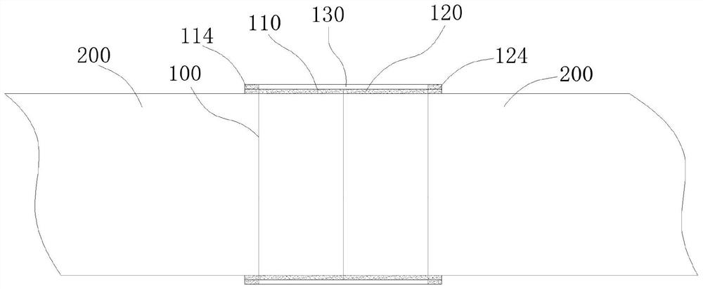
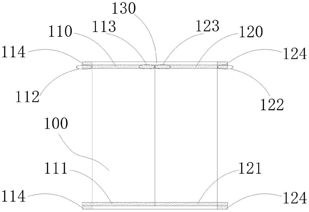
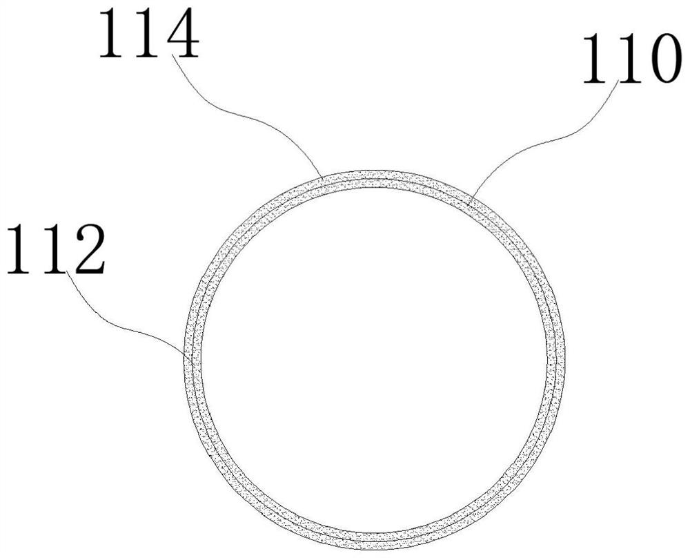
[0107] Example 1, please refer to figure 1 , figure 2 with image 3 .
[0108] A pipe connector 100, comprising a connecting pipe 130 and a connecting pipe lining part, the connecting pipe 130 is a pipe body, the connecting pipe lining part is arranged on the inner wall of the connecting pipe 130, and the connecting pipe lining part is arranged on a pipe connected in series Between the outer walls of the two external pipes 200 and the inner wall of the connecting pipe, solids, liquids, and gases cannot enter the two external pipes 200 connected in series from the joints of the two external pipes 200 connected in series.
[0109] The connecting pipe lining part comprises a connecting pipe lining part first part 110 and a connecting pipe lining part second part 120, and the connecting pipe lining part first part 110 and the connecting pipe lining part second part 120 are arranged on the inner wall of the connecting pipe Above, the first part of the connecting pipe lining par...
Embodiment 2
[0120] Example 2, please refer to Figure 4 , based on Embodiment 1, the difference is that: the two inner lining parts of the connecting pipe are both provided with internal baffles.
[0121] The first part 110 of the connecting pipe lining part also has an internal stop part 115 of the first part of the connecting pipe lining part. The part 115 is arranged on the inner wall of the second end part of the liner part of the first part of the connecting pipe lining part, and is connected with the port of the external pipe.
[0122] The liner part of the first part of the connecting pipe inner lining part, the outer stop part 114 of the first part of the connecting pipe inner lining part and the inner stop part 115 of the first part of the connecting pipe inner lining part are made of elastic material.
[0123] The second part 120 of the connecting pipe lining part also has an internal stop part 125 of the second part of the connecting pipe lining part. The part 125 is arranged...
Embodiment 3
[0127] Example three, please refer to Figure 5 .
[0128] This embodiment is based on the second embodiment. The improvement of this embodiment is that corrugated rings are arranged inside and outside the lining part of the connecting pipe, the thickness of the lining part of the connecting pipe is uneven, the axial cross section of the lining part of the connecting pipe is trapezoidal, and A hollow cavity is provided in the lining part of the connecting pipe, and the specific technical scheme is described as follows:
[0129] A pipe connector 100, comprising a connecting pipe 130 and a connecting pipe lining part, the connecting pipe 130 is a pipe body, the connecting pipe lining part is arranged on the inner wall of the connecting pipe 130, and the connecting pipe lining part is arranged on a pipe connected in series Between the outer wall of the two external pipes and the inner wall of the connecting pipe, solids, liquids, and gases cannot enter the interior of the two ex...
PUM
 Abstract
Description
Claims
Application Information