Eureka AIR delivers breakthrough ideas for toughest innovation challenges, trusted by R&D personnel around the world.

Illuminating lamp for ship

A technology for lighting lamps and ships, applied in lighting devices, lighting auxiliary devices, lighting and heating equipment, etc., can solve the problems of inconvenient lighting replacement, frequent manual replacement, labor-consuming and other problems, and reduce maintenance or replacement of lighting lamp bodies. frequency, saving the time of installing and disassembling the lighting body, and facilitating maintenance or replacement.

Active Publication Date: 2021-04-02
HAIXING MARITIME ELECTRIC GROUP
View PDF5 Cites 0 Cited by
  • Summary
  • Abstract
  • Description
  • Claims
  • Application Information

AI Technical Summary

Problems solved by technology

[0003] Existing lighting fixtures in ships are generally fixedly installed at a fixed position on the top of the inner wall of the hall. When the lighting lamps inside the ship are damaged, they need to be replaced manually in time, and the lighting lamps inside the ship generally require long-term lighting. The lamp is very easy to be damaged, resulting in frequent manual replacement, which consumes manpower, increases the maintenance cost, and affects the normal lighting use; and the existing marine lighting is generally fixed and installed on the top of the inner room by fixing screws, and one person needs to hold it by hand during installation. Another person fixes the installation with screws. The installation is time-consuming and laborious, and it is not convenient to replace the lighting. Therefore, we propose a lighting lamp for ships

Method used


Image

  • Illuminating lamp for ship
  • Illuminating lamp for ship
  • Illuminating lamp for ship

Examples


Embodiment Construction

[0021]Next, the technical solutions in the embodiments of the present invention will be apparent from the embodiment of the present invention, and it is clearly described, and it is understood that the described embodiments are merely embodiments of the present invention, not all of the embodiments. Based on the embodiments of the present invention, there are all other embodiments obtained without making creative labor without making creative labor premises.

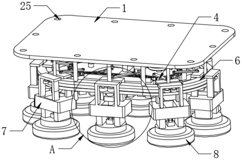
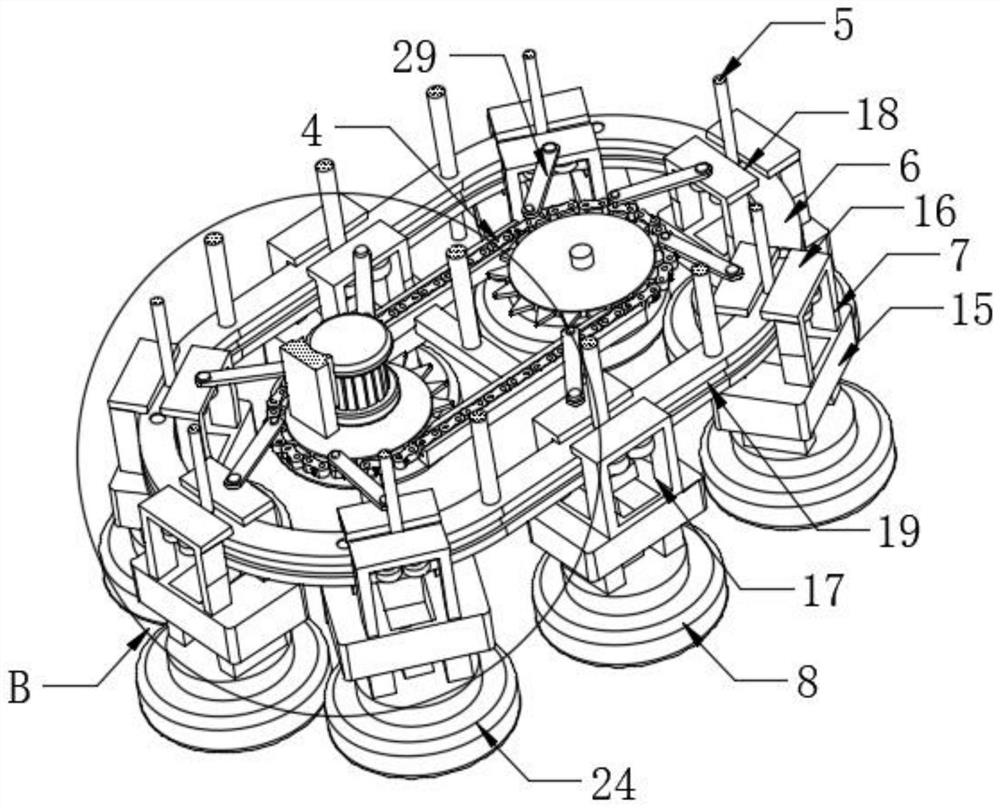
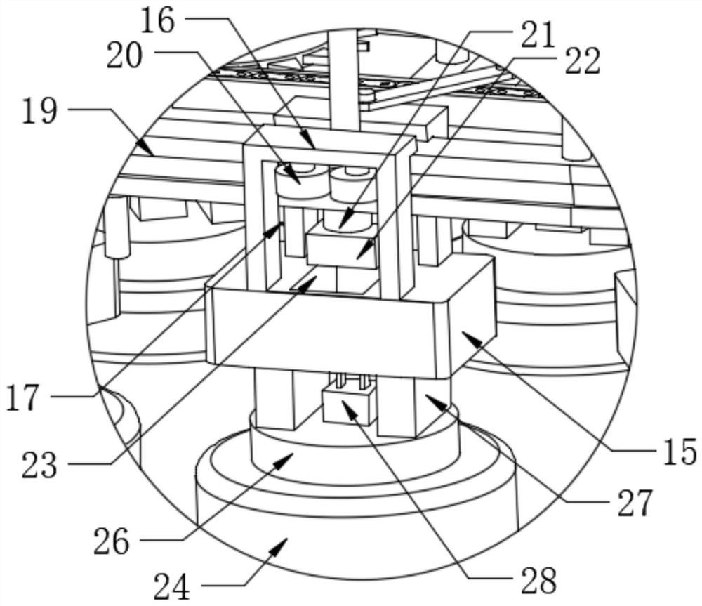
[0022]Seefigure 1 ,figure 2 withFigure 4 The present invention provides a technical solution: a ship light, including mounting plate 1 and a drive mechanism 4, and a drive mechanism 4 is provided at the bottom of the mounting plate 1, further comprising: a fixed bar 2, a fixing plate 3, and sliding 4, the moving block 7 and the lighting mechanism 8, the bottom center of the mounting plate 1 is fixedly mounted, and the fixed bar 2 is fixedly mounted at one end of the mounting plate 1, and the drive mechanism 4 is disposed. The out...


PUM


Abstract

The invention discloses an illuminating lamp for a ship. The illuminating lamp comprises a mounting plate and a driving mechanism, wherein the bottom of the mounting plate is provided with the drivingmechanism. The illuminating lamp further comprises a fixed rod, a fixed plate, a sliding way, a movable block and an illuminating mechanism; the fixed rod is fixedly mounted in the center of the bottom of the mounting plate; the illuminating lamp can drive the movable block on the sliding way to move through the driving mechanism; the movable block can drive the multiple sets of lighting lamps toslide; when the lighting lamp body of the power-on socket at the bottom of the sliding way breaks down, the other set of lighting lamp body can be controlled to work at the power-on position; and when the multiple sets of lighting lamp bodies on the sliding way break down, maintenance workers can overhaul or replace the lighting lamp bodies in a unified mode, so that the frequency in overhaulingor replacing the illuminating lamp body is reduced, and the maintenance cost is saved; and meanwhile, the illuminating lamp body can be installed only by one person, so that maintenance workers can overhaul or replace the illuminating lamp body conveniently, and the time in installing and detaching the illuminating lamp body is saved.

Description

Technical field[0001]The present invention relates to the field of ship lighting techniques, and is specifically a laser light.Background technique[0002]The ship is a normal transportation in geographic water. In addition, civilians are generally called boats, military boats are called ships, and small boats are called boats or boats, and they are shaped into ships or boats. They mainly include accommodation. Space, support processing and drainage structure, with advanced or self-propelled propulsion systems, the shape is generally conducive to flow linearity of fluid resistance, and the lighting is required to illuminate in the ship.[0003]Existing ship lighting fixtures are typically fixed in a fixed position in the top of the hall in the hall. When the light inside the ship is damaged, it needs to be replaced in time, while the light inside the ship generally takes a long time, lighting. The lamp is very easy to damage, causing manual replacement more frequent, labor-consuming man...

Claims


Application Information

Patent Timeline
Patent Type & Authority Applications(China)
IPC IPC(8): F21S41/00F21S43/00F21V19/02F21V21/34F21V23/06F21W107/20
CPCF21S41/00F21S43/00F21V19/02F21V21/34F21V23/06F21W2107/20Y02B20/40
Inventor 韩洋
Owner HAIXING MARITIME ELECTRIC GROUP
Why Eureka
Eureka Blog
Learn More