
On-line monitoring device for transmission line

A monitoring device, transmission line technology, applied in circuit devices, electrical components, information technology support systems, etc., can solve the problems of product incompatibility, strong combination, different product focus, etc., to solve the problems of mutual compatibility and integration. Difficulty, the effect of improving flexibility

Inactive Publication Date: 2011-10-19
STATE GRID ELECTRIC POWER RES INST +2
View PDF3 Cites 2 Cited by
  • Summary
  • Abstract
  • Description
  • Claims
  • Application Information

AI Technical Summary

Problems solved by technology

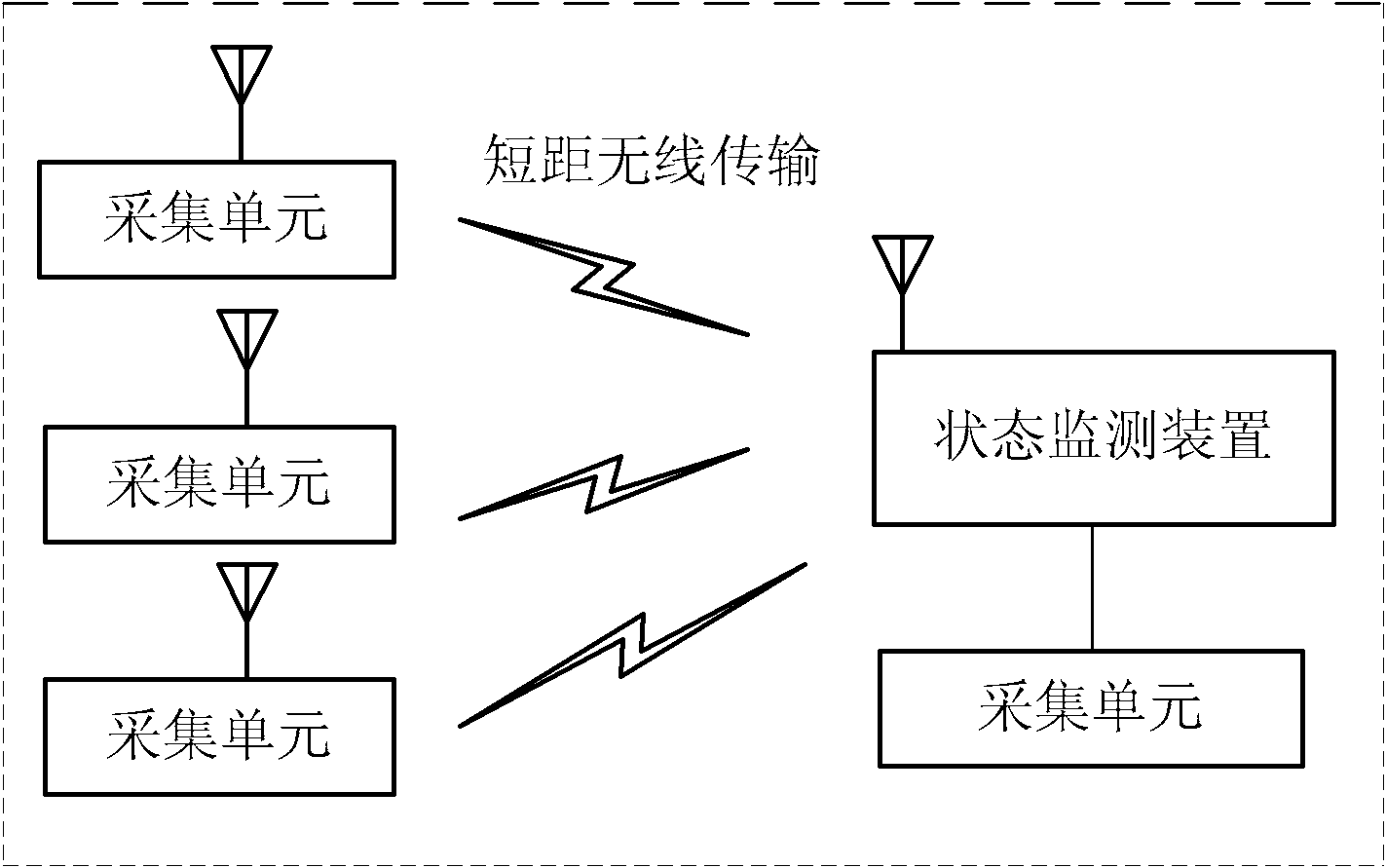
[0003] At present, there are many online monitoring products for the status of transmission lines, but they are basically aimed at a single state quantity or a few related state quantities. Few manufacturers can launch a comprehensive and comprehensive system. On the one hand, it is because the technical expertise of each manufacturer is different, and the focus of the product is different; on the other hand, it is also because the traditional system framework adopts a tightly coupled working mode between the data acquisition unit and the state monitoring device, so that the data acquisition unit and the state monitoring device The combination between them is too strong, and the products of various manufacturers are not compatible with each other, especially for some wireless data acquisition units for the state quantity of the ground wire. Therefore, the wireless data acquisition unit produced by one manufacturer cannot be interconnected with the condition monitoring devices of other manufacturers, which often leads to the installation of several sets of condition monitoring devices on a tower due to the need to monitor several different state quantities. It has brought a lot of trouble to the integration, management and maintenance of the telemetry system, and also caused the system cost to remain high. At the same time, excessive installation of online monitoring devices has brought certain hidden dangers to the safety of the transmission tower itself.

Method used


Image

  • On-line monitoring device for transmission line
  • On-line monitoring device for transmission line
  • On-line monitoring device for transmission line

Examples


Embodiment Construction

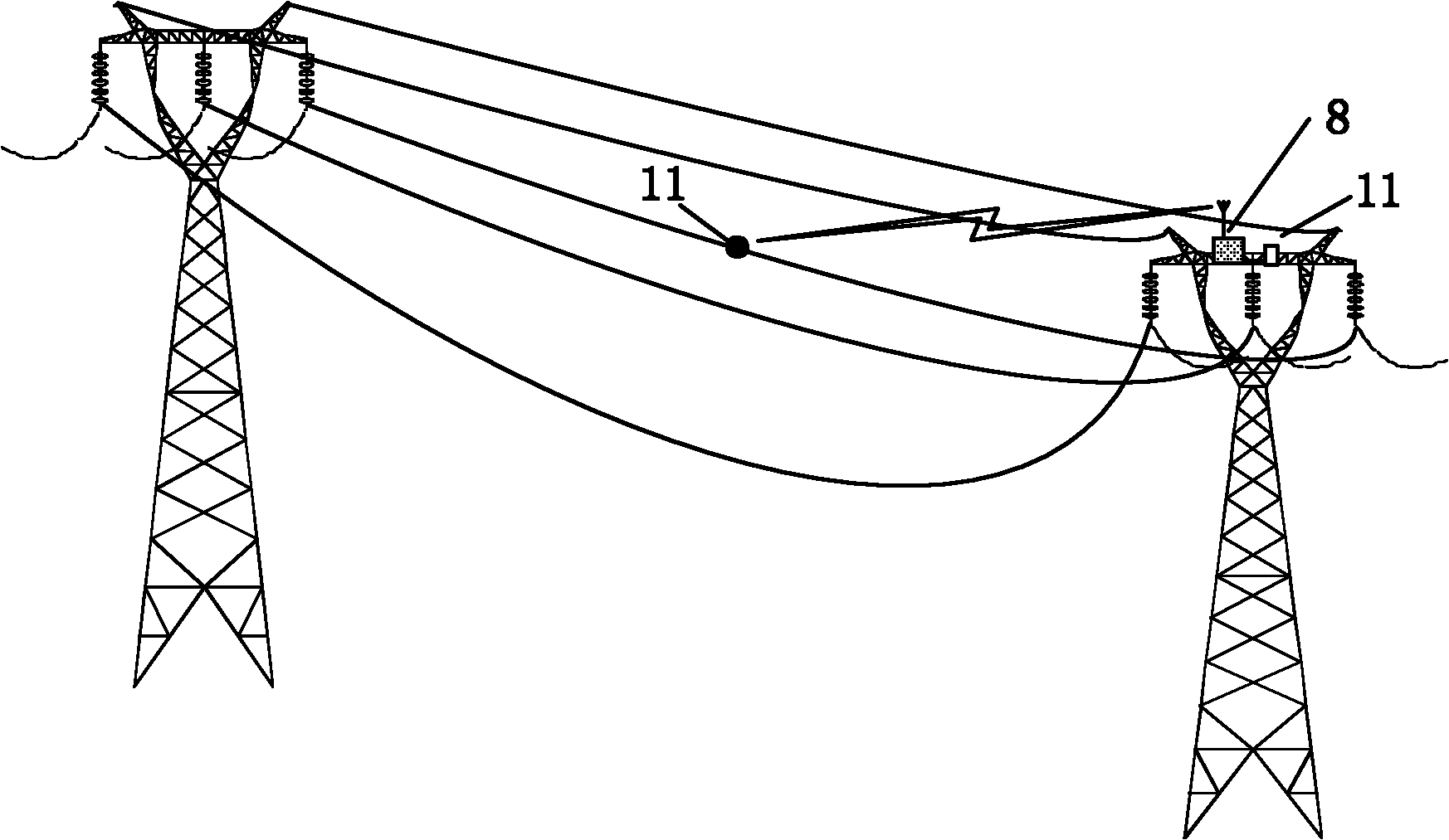
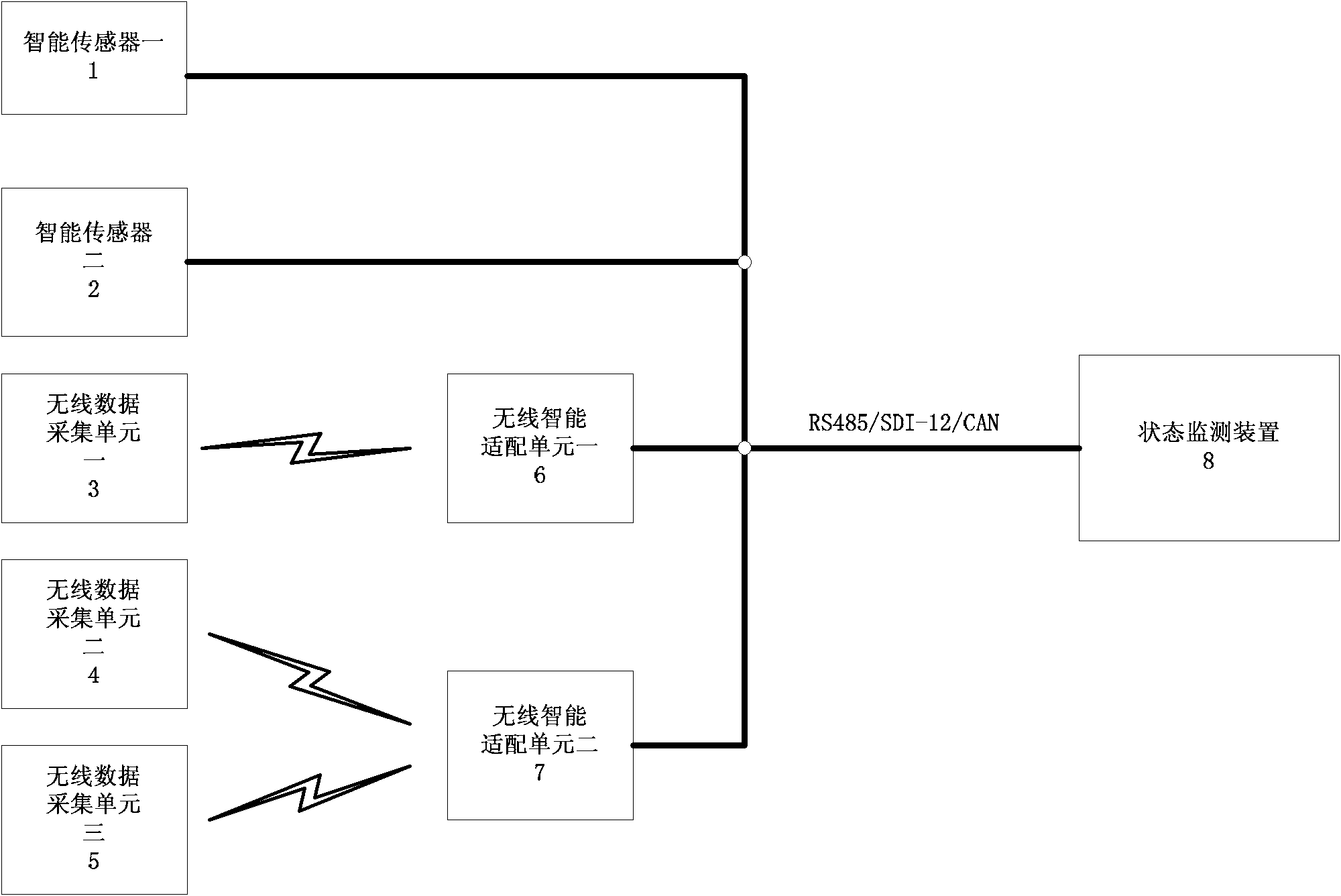
[0017] The state monitoring device in the technical solution of the present invention provides RS485, SDI-12 or CAN and other hardware bus access methods externally, and all data acquisition units are connected through the above-mentioned hardware bus mode, and the communication protocol adopts open standards such as SDI-12 and MODBUS letter of agreement. Among them, the wired data acquisition unit provides the above-mentioned bus interface through technological transformation and becomes a bus-type smart sensor; the wireless data acquisition unit 11 provides the above-mentioned bus interface by introducing a wireless intelligent adaptation unit, and the final overall system framework is as follows image 3 shown.

[0018] Among them, smart sensor one 1 and smart sensor two 2 are wired sensors installed on the tower, providing standard RS485, SDI-12 or CAN bus interface 9; wireless data acquisition unit one 3 and wireless intelligent adaptation unit one 6 constitute A single-...


PUM


Abstract

The invention discloses an on-line monitoring device for a transmission line. The on-line monitoring device comprises a condition monitoring device and is characterized in that the condition monitoring device comprises an RS485, an SDI-12 (standard data interface) or a CAN (controller area network) hardware bus interface, a wire sensor which is arranged on a tower is provided with the same hardware bus interface with the condition monitoring device and is communicated with the condition monitoring device through the RS485, the SDI-12 or the CAN hardware bus interface; a wireless data acquisition unit is in wireless communication with a wireless intelligent adapter unit, the wireless intelligent adapter accesses the condition monitoring device through the RS485, the SDI-12 or the CAN hardware bus interface. The intelligent sensor provided by the invention has universal applicability and can better solve the problems of difficult integration, difficult maintenance and overlapping investment and the like in the traditional system.

Description

technical field [0001] The invention relates to an on-line monitoring device for a power transmission line, which belongs to the technical field of power transmission and distribution in electric power systems. Background technique [0002] The status monitoring system of overhead transmission lines integrates communication control, database platform and information release, etc. It is used for information processing such as reception, storage, calculation, etc., provides information on the status of power facilities or the environment, and monitors, warns, and assists the operating status of transmission lines. The general term for software platforms for decision-making and data analysis. In the transmission line on-line monitoring system, the state quantities that need to be monitored involve a very wide range, including the monitoring of various state quantities such as ground wires, towers, fittings, insulators, meteorology, images, environment, foundation, etc., a set o...

Claims


Application Information

Patent Timeline
IPC IPC(8): H02J13/00
CPCY04S40/126Y02E60/00
Inventor 曹翊军曹年红孙骏薛升宁刘果
Owner STATE GRID ELECTRIC POWER RES INST
Learn More