dfig Impeller Unbalanced Fault Diagnosis Method Based on Current Signal Coordinate Transformation
A technology of coordinate transformation and current signal, which is applied in the direction of measuring electricity, measuring electric variables, and testing motor generators. It can solve problems such as low reliability and high cost, and achieve the effect of easy implementation and good application prospects.
- Summary
- Abstract
- Description
- Claims
- Application Information
AI Technical Summary
Problems solved by technology
Method used
Image
Examples
Embodiment 1
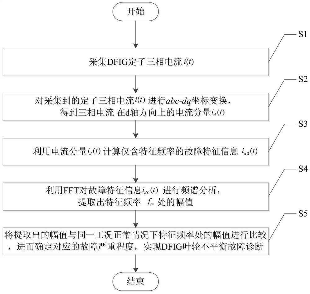
[0041] like figure 1 As shown, the DFIG impeller unbalance fault diagnosis method based on current signal coordinate transformation includes the following steps:
[0042] S1. Collect the three-phase current i(t) of the DFIG stator;
[0043] S2. Perform abc-dq coordinate transformation on the collected stator three-phase current i(t) to obtain the current component i of the three-phase current i(t) in the d-axis direction d (t);
[0044] S3, using the current component i d (t) Calculate only the eigenfrequency f m The fault characteristic information i of d0 (t);
[0045] where f m =ω m / 2π, ω m is the angular velocity of the impeller movement;
[0046] S4. Use FFT to analyze the fault characteristic information i d0 (t) Perform spectrum analysis to extract the characteristic frequency f m Amplitude at ;
[0047] S5. Compare the extracted amplitude with the amplitude at the characteristic frequency under the same working condition under normal conditions, and then d...
Embodiment 2
[0063] In this example, under the condition of DFIG impeller unbalanced fault operation, the influence of the impeller unbalanced given stator current is analyzed:
[0064] When the impeller is unbalanced, the shaft torque output by the fan can be expressed as:
[0065] The shaft torque T output by the fan can be expressed as:
[0066] T=T 0 +T v sin(ω m t) (4)
[0067] In the formula: t is time; T 0 is the aerodynamic torque generated by the fan; T v is the magnitude of torque ripple caused by unbalanced faults, ω m is the fan speed.
[0068] The DFIG is equivalent to a single-mass model, and its equation of motion is:
[0069]
[0070] In the formula: H M is the equivalent inertia time constant; T e is the electromagnetic torque; D M The damping coefficient is negligible.
[0071] According to equations (4) and (5), it can be seen that under the condition of unbalanced impeller and stable operation, T e can be expressed as:
[0072] T e =T e0 +T ev sin(...
Embodiment 3
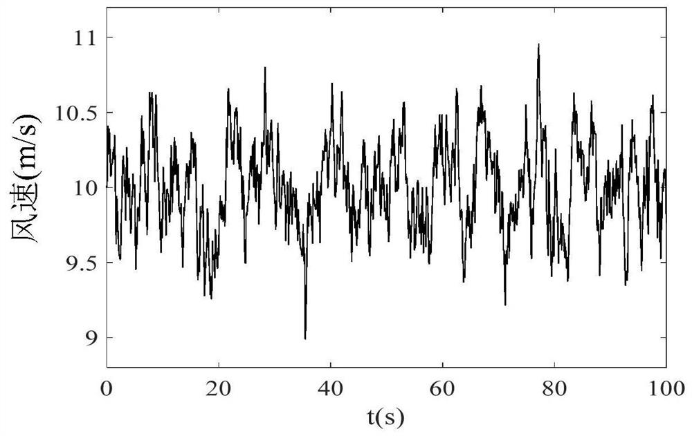
[0082] The following is a simulation of the actual operating environment of the fan, and a wind speed model with a turbulence intensity of 3% and an average wind speed of 10m / s is constructed, such as figure 2 shown.
[0083] In order to quantitatively express the degree of impeller unbalance failure, the impeller unbalance factor F is defined as:
[0084] F=T v / T 0 (10)
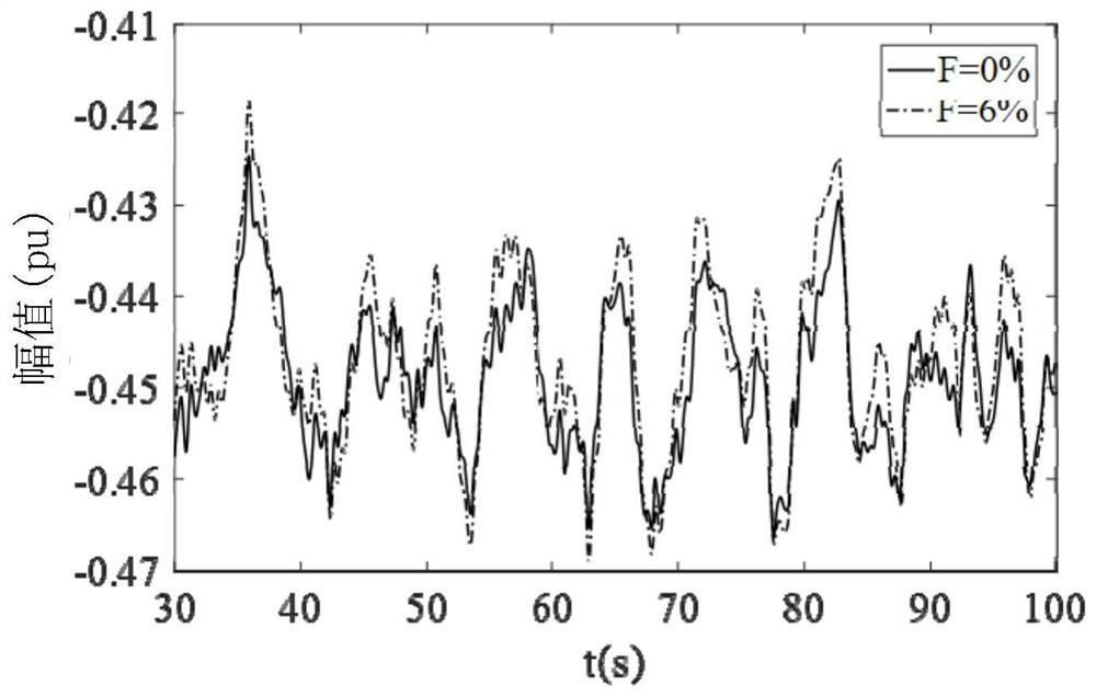
[0085] Under the above-mentioned turbulent wind speed environment, the DFIG under two conditions of normal impeller F=0% and F=6% under impeller failure are simulated and studied respectively.
[0086] image 3 is the fault characteristic current i under the normal operation of the impeller and the unbalanced fault d0 (t) time domain signal; Figure 4 is the fault characteristic current i under the normal operation of the impeller and the unbalanced fault d0 (t) spectrogram; Figure 5 , 6 are the time domain signals of the stator A-phase current under the normal operation of the impeller and the ...
PUM
 Abstract
Description
Claims
Application Information
 - R&D
- Intellectual Property
- Life Sciences
- Materials
- Tech Scout
- Unparalleled Data Quality
- Higher Quality Content
- 60% Fewer Hallucinations
Browse by: Latest US Patents, China's latest patents, Technical Efficacy Thesaurus, Application Domain, Technology Topic, Popular Technical Reports.
© 2025 PatSnap. All rights reserved.Legal|Privacy policy|Modern Slavery Act Transparency Statement|Sitemap|About US| Contact US: help@patsnap.com


