
Method for identifying grounding electrode line fault of high-voltage direct current power transmission system

A power transmission system, high-voltage direct current technology, applied in the direction of measuring electricity, measuring electrical variables, measuring resistance/reactance/impedance, etc., can solve the problems of difficult project implementation, high hardware requirements, overload rupture of ground electrode lead 1, etc. Fast and effective processing, high detection sensitivity, and easy on-site implementation

Active Publication Date: 2018-11-20
SOUTHWEST JIAOTONG UNIV
View PDF9 Cites 4 Cited by
  • Summary
  • Abstract
  • Description
  • Claims
  • Application Information

AI Technical Summary

Problems solved by technology

For example: Since Xing’an DC Transmission Project was put into operation in 2007, there have been too many unbalanced ground electrode lines (the current deviation on the two parallel lines is large) protection actions, resulting in bipolar or unipolar blocking events
In July 2015, when Binjin DC was operating at full load, pole 2 was blocked, and the current of Binjin and Fufeng DC's common grounding pole line increased instantaneously, causing the grounding pole lead 1 to break due to overload
When a short-circuit ground fault occurs at the back of the protective ground electrode line, the current deviation of the two ground electrode lines is small enough to determine that the fault has occurred; and the transition resistance of the short-circuit ground fault (the resistance formed by various debris between the short-circuit point and the ground) ) will also reduce the current deviation of the two grounding electrode lines, resulting in low protection sensitivity, and the grounding electrode line may run with "disease" for a long time, posing safety hazards
In order to solve the problem of low protection sensitivity when a high-resistance, remote grounding fault occurs in the grounding electrode line of the HVDC power transmission system, high-frequency signals can be injected into the grounding electrode line to monitor the high-frequency impedance or electrical quantity of the line to identify the fault
However, the drift and deviation of the parameters of the ground electrode line in the high-frequency signal environment will seriously affect the impedance monitoring value, which objectively brings difficulties to the setting of such criteria; at the same time, this method requires accurate high-frequency signal injection equipment and sensitive The high-frequency signal detection device has high requirements on hardware and is difficult to implement in engineering

Method used


Image

  • Method for identifying grounding electrode line fault of high-voltage direct current power transmission system
  • Method for identifying grounding electrode line fault of high-voltage direct current power transmission system
  • Method for identifying grounding electrode line fault of high-voltage direct current power transmission system

Examples


Embodiment

[0036]A specific embodiment of the present invention is a method for identifying a fault in a ground electrode line of a high-voltage direct current transmission system, the steps of which are as follows:

[0037] A. Data collection

[0038] The electrical measuring device of the grounding electrode system is installed on the neutral busbar of the converter station of the HVDC power transmission system. A current signal I 1 (t) and the second current signal I of the second ground electrode line 2 (t), and the collected voltage signal U(t), the first current signal I 1 (t) and the second current signal I 2 (t) sent to the relay protection device of the system, where t represents the sampling time;

[0039] B. Data processing

[0040] The relay protection device of the system performs the following processing on the data sent by the electrical measuring device:

[0041] Using the full-wave Fourier algorithm to extract the voltage signal U(t) and the first current signal I ...


PUM


Abstract

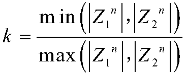
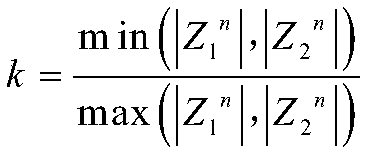
The invention provides a method for identifying a grounding electrode line fault of a high-voltage direct current power transmission system. The steps mainly include: A, data acquisition, an electrical measurement device at a neutral bus measuring point of a grounding electrode system acquiring front-end voltage signals of grounding electrode lines and current signals of the two grounding electrode lines in real time; B, data processing, characteristic harmonic components of the grounding electrode line front-end voltage signals and the grounding electrode line current signals being extractedthrough a full-wave Fourier algorithm; C, calculation of a characteristic harmonic measured impedance amplitude ratio, the characteristic harmonic voltage amplitude of the front ends of the groundingelectrode lines and the characteristic harmonic current amplitude of the two grounding electrode lines being utilized to calculate the characteristic harmonic measured impedance amplitude of the two grounding electrode lines separately, thereby obtaining the characteristic harmonic measured impedance amplitude ratio; and D, line short-circuit fault identification, the characteristic harmonic measured impedance amplitude ratio being smaller than or equal to a set threshold value, that is, occurrence of a fault of the grounding electrode line being judged. The method has the advantages of high resistance to transition resistance, high detection sensitivity, low implementation cost and easy engineering realization.

Description

technical field [0001] The invention relates to a fault identification method in relay protection of an electric power system, in particular to a fault identification method for a ground electrode line of a high-voltage direct current transmission system. Background technique [0002] The grounding electrode is an important part of the HVDC transmission system, which plays the role of providing a path for the unbalanced current and clamping the neutral point voltage. In order to avoid the impact of DC bias on the converter station equipment, the grounding pole is usually not grounded at the nearest converter station equipment, but connects the neutral point of the converter station equipment to a remote place through two parallel overhead lines of hundreds of kilometers grounding. Its ground electrode line is long and the environment experienced is complex, resulting in a high failure rate. In actual engineering, there are many incidents where ground electrode line faults ...

Claims


Application Information

Patent Timeline
Patent Type & Authority Applications(China)
IPC IPC(8): G01R31/02G01R27/08
CPCG01R27/08G01R31/50
Inventor 林圣孙沛瑶刘磊何正友
Owner SOUTHWEST JIAOTONG UNIV
Learn More