
Circuit board mounting device

A board mounting and circuit technology, applied in the field of circuit board mounting devices, can solve problems such as increasing PCB board pollution

Active Publication Date: 2021-04-02
TCL KING ELECTRICAL APPLIANCES HUIZHOU
View PDF3 Cites 0 Cited by
  • Summary
  • Abstract
  • Description
  • Claims
  • Application Information

AI Technical Summary

Problems solved by technology

[0003] The main purpose of the present invention is to propose a circuit board chip loading device, which aims to solve the problem of frequent contact between the PCB board and the human body during the process of manually inserting the PCB board into the SMT loading and unloading rack in the prior art, which increases the pollution of the PCB board. question

Method used


Image

  • Circuit board mounting device
  • Circuit board mounting device
  • Circuit board mounting device

Examples


Embodiment Construction

[0029] The following will clearly and completely describe the technical solutions in the embodiments of the present invention with reference to the accompanying drawings in the embodiments of the present invention. Obviously, the described embodiments are only part of the embodiments of the present invention, not all of them. Based on the embodiments of the present invention, all other embodiments obtained by persons of ordinary skill in the art without creative efforts fall within the protection scope of the present invention.

[0030] It should be noted that if there is a directional indication (such as up, down, left, right, front, back...) in the embodiment of the present invention, the directional indication is only used to explain the relationship between the components in a certain posture. If the specific posture changes, the directional indication will also change accordingly.

[0031] In addition, if there are descriptions involving "first", "second" and so on in the...


PUM


Abstract

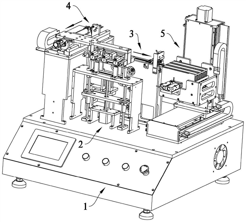
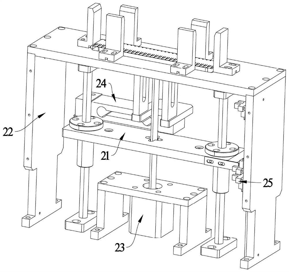
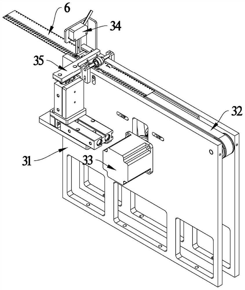
The invention discloses a circuit board mounting device. The device comprises a pedestal which is provided with a feeding assembly, a conveying assembly, a carrying assembly, and a stacking assembly,wherein a jacking part is arranged in the feeding assembly and used for jacking upwards in the Z-axis direction; the conveying assembly is arranged on the side face of the feeding assembly and provided with a conveying line in the X-axis direction; the carrying assembly is arranged on one side of the feeding assembly, the carrying assembly is provided with a suction part, and the suction part is used for moving from the position above the jacking part to the position above the conveying line in the Y-axis direction; the stacking assembly is arranged on the side, away from the carrying assembly, of the conveying assembly. According to the circuit board mounting device, a problem that in the prior art, in the process that a PCB is manually inserted into an SMT feeding and discharging frame,the PCB makes frequent contact with a human body, and consequently pollution to the PCB is increased is solved, pollution of human factors to the PCB in the PCB inserting process is avoided, the finished product rate and the conversion rate in subsequent production are effectively increased, and the cost is reduced.

Description

technical field [0001] The invention relates to the technical field of circuit board processing and manufacturing, in particular to a circuit board chip loading device. Background technique [0002] During the handling process of PCB (Printed Circuit Board, printed circuit board), SMT (Surface Mounted Technology, surface mount technology) loading and unloading racks are required to hold PCB boards. SMT loading and unloading racks are widely used in automatic loading and unloading machines, acid-resistant and resistant Alkali, oil resistance, high temperature resistance, non-toxic and tasteless, easy to clean, the use of SMT loading and unloading racks makes the turnover of circuit boards convenient, neatly stacked, and easy to manage. In addition, SMT loading and unloading racks can be matched with various logistics containers and workstations, and are used in various warehouses, production sites and other occasions. The traditional operation method is to manually insert th...

Claims


Application Information

Patent Timeline
Patent Type & Authority Applications(China)
IPC IPC(8): H05K3/34H05K3/00H05K13/00
CPCH05K3/34H05K3/0008H05K13/0061
Inventor 郭国军
Owner TCL KING ELECTRICAL APPLIANCES HUIZHOU
Learn More