
Air duct structure, micro-module machine room and micro-module control method

A micro-module and air duct technology, which is applied to the structural parts of electrical equipment, cooling/ventilation/heating renovation, electrical components, etc. Avoid the waste of air supply and the effect of large temperature difference

Pending Publication Date: 2021-04-02
SHENZHEN KEXIN COMM TECH
View PDF0 Cites 1 Cited by
  • Summary
  • Abstract
  • Description
  • Claims
  • Application Information

AI Technical Summary

Problems solved by technology

[0010] The technical problem to be solved by the present invention is to provide an air duct structure for the problem that the existing micro-module data center cannot accurately supply air to the equipment in the micro-module, resulting in a large temperature difference in the air supply between the equipment , micro-module computer room and micro-module control method

Method used


Image

  • Air duct structure, micro-module machine room and micro-module control method
  • Air duct structure, micro-module machine room and micro-module control method
  • Air duct structure, micro-module machine room and micro-module control method

Examples


Embodiment Construction

[0042] In order to make the technical problems, technical solutions and beneficial effects solved by the present invention clearer, the present invention will be further described in detail below in conjunction with the accompanying drawings and embodiments. It should be understood that the specific embodiments described here are only used to explain the present invention, not to limit the present invention.

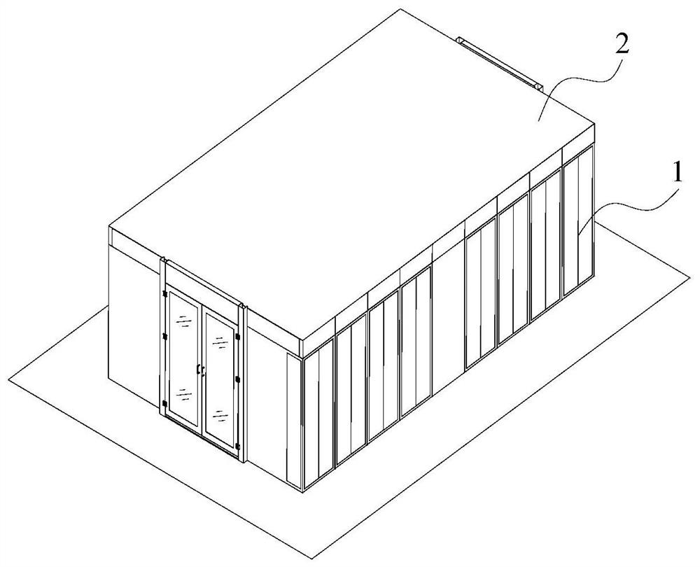
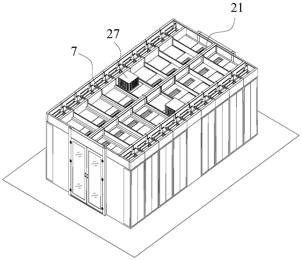
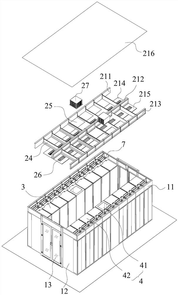
[0043] Such as Figure 1 to Figure 6 As shown, an embodiment of the present invention provides an air duct structure 2 including a main frame 21 , a static pressure channel and a plurality of damping plates 24 . The main frame 21 is arranged on the top of the cabinet group, the main frame 21 is provided with an air inlet 25 and a plurality of air outlets, the static pressure channel is arranged on the main frame 21, and the air flow enters through the air inlet 25 The static pressure channel flows out of the static pressure channel through a plurality of air outlets, an...


PUM


Abstract

The invention belongs to the technical field of communication integrated equipment, and particularly relates to an air duct structure, a micro-module machine room and a micro-module control method. The air duct structure comprises a main framework, a static pressure channel and a plurality of damping plates; the main framework is arranged at the top of a cabinet group, the main framework is provided with an air inlet and a plurality of air outlets, the static pressure channel is arranged on the main framework, airflow enters the static pressure channel through the air inlet and flows out of the static pressure channel through the plurality of air outlets, and the air outlets are arranged above a single cabinet in a one-to-one correspondence manner; and the multiple damping plates are arranged at intervals in the extending direction of the static pressure channel, the damping plates are movably connected to the main framework, and the damping plates ascend and descend so that the pressure difference between each air outlet and the corresponding air inlet can be within the preset pressure difference range. Through the plurality of damping plates with different heights, the air pressure and the air volume in the static pressure channel are balanced, the air flow temperature difference in the static pressure channel is reduced, accurate air supply is carried out as required, the temperature difference between cabinets is reduced, and the air supply waste is avoided.

Description

technical field [0001] The invention belongs to the technical field of communication integration equipment, and in particular relates to an air duct structure, a micro-module machine room and a micro-module control method. Background technique [0002] With the development of communication technology, the 5G market, network broadband market and business volume continue to grow, the power consumption capacity of 5G equipment is increasing exponentially, and the power consumption cost is also increasing exponentially. The micro-module data center integrates the power distribution, air conditioning, backup power, wiring, cabinets, fire protection, monitoring, lighting and other systems of the traditional computer room into one, realizing the rapid and flexible deployment of the system, which not only reduces the construction period of 5G, but also It can better adapt to changes in servers such as cloud computing, virtualization, centralization, and high density, improve the ope...

Claims


Application Information

Patent Timeline
Patent Type & Authority Applications(China)
IPC IPC(8): H05K7/20
CPCH05K7/20745H05K7/20836
Inventor 曾剑鹏刘刚可罗华平陈宇峰陈登志赵毓毅
Owner SHENZHEN KEXIN COMM TECH
Learn More