Hot galvanizing pot smoke exhaust gas collecting device

A gas-collecting device and hot-dip galvanizing technology, applied in the field of material devices, can solve problems such as difficult cleaning, failure to work normally, and blockage of the dust removal system, so as to save production and operation space, facilitate production and operation, and reduce operation and maintenance costs Effect

Active Publication Date: 2020-12-01
安徽徽柏环保科技有限公司
View PDF7 Cites 2 Cited by
  • Summary
  • Abstract
  • Description
  • Claims
  • Application Information

AI Technical Summary

Problems solved by technology

Especially the smoke and dust on the surface of the filter material is not easy to be separated even by pulse injection, which will cause long-term blockage of the dust collector, greatly reduce the air volume, and lead to a significant drop in the efficiency of the dust removal system;
[0008] (3) Difficulty in operation and maintenance and high cost: due to the blockage of the filter material by smoke and dust, it needs to be cleaned in time. According to the experience of technicians in the field, conventional polyester needle-punched felt bags or polyester fiber filter cartridges need to be cleaned once every 3 days. Replace once a month. The coated needle-punched felt bag or polyester fiber filter cartridge needs to be cleaned once a week and replaced once every 6 months, otherwise the dust removal system will be completely blocked and

Method used


Image

  • Hot galvanizing pot smoke exhaust gas collecting device
  • Hot galvanizing pot smoke exhaust gas collecting device
  • Hot galvanizing pot smoke exhaust gas collecting device

Examples


Embodiment Construction

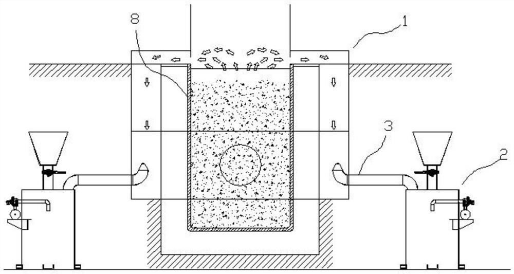
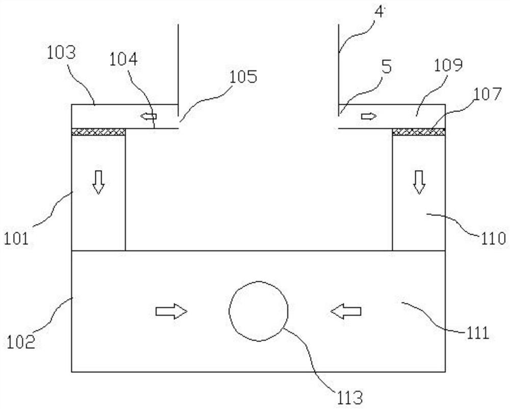
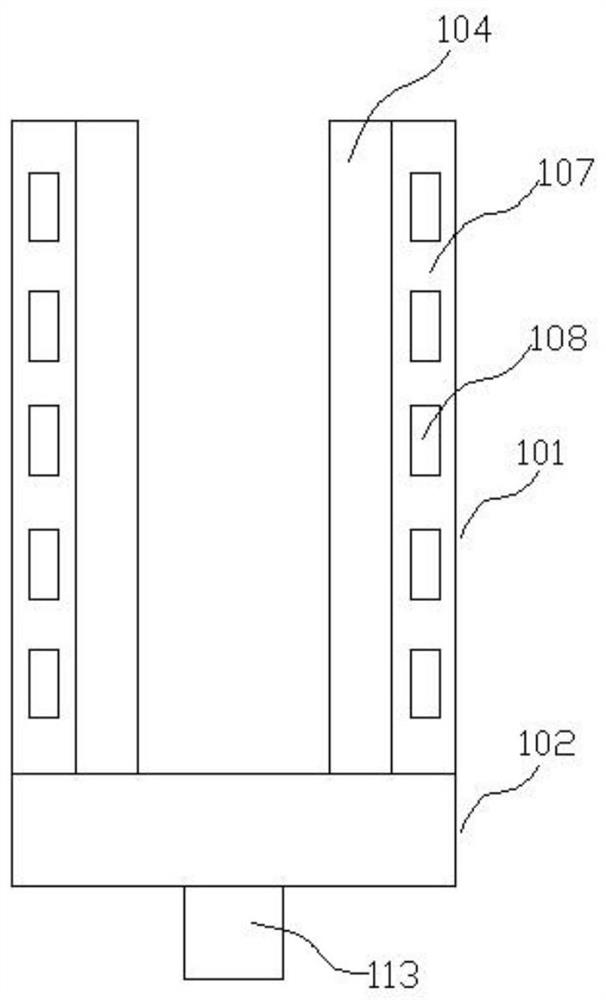
[0047] In order to make the purpose, technical solutions and advantages of the embodiments of the present invention more clear, the technical solutions in the embodiments of the present invention will be clearly and completely described below in conjunction with the drawings in the embodiments of the present invention.

[0048] In the description of the present invention, it should be noted that unless otherwise specified, the meaning of "plurality" is two or more; the terms "upper", "lower", "left", "right", "inner ", "outside", "front end", "rear end", "top", "bottom" and other indicated orientations or positional relationships are based on the orientations or positional relationships shown in the drawings, and are only for the convenience of describing the present invention and simplifying the Describes, but does not indicate or imply that the device or element referred to must have a specific orientation, be constructed in a specific orientation, and operate in a specific o...


PUM


Abstract

The invention discloses a hot galvanizing pot smoke exhaust gas collecting device, and relates to the technical field of zinc pot smoke exhaust gas treatment. The hot galvanizing pot smoke exhaust gascollecting device comprises a gas collecting hood and powder spraying equipment, the gas collecting hood comprises gas collecting boxes and an air mixing box, and a conveying pipeline is connected between the powder spraying equipment and each gas collecting box; each gas collecting box comprises a gas collecting strip opening, and an air outlet is formed in each gas collecting box; and an innerspace of each gas collecting box is divided into an air equalizing chamber and a smoke dust channel from top to bottom, each smoke dust channel is communicated with the corresponding air outlet, the air mixing box comprises an air mixing channel arranged inside and a pair of air inlets communicated with the air mixing channel, the air inlets are communicated with the air outlets in the corresponding gas collecting boxes, and an air exhaust pipeline communicated with the air mixing channel is arranged on the air mixing box. The hot galvanizing pot smoke exhaust gas collecting device is constructed around a zinc pot heat preservation layer, the influence on production operation is reduced to the maximum extent, meanwhile, the viscosity of smoke particles of a hot galvanizing pot can be greatly reduced, the dust removal efficiency of a dust remover is improved, the service life of a filter material is prolonged, and the maintenance period is prolonged.

Description

technical field [0001] The invention relates to the technical field of hot-dip galvanizing pot smoke and waste gas purification, in particular to a device that can effectively collect the smoke and dust waste gas discharged from a hot-dip galvanizing pot and mix it with lubricating graphite, quicklime or talcum powder and other substances. Background technique [0002] The temperature of the melt in the galvanizing pot is about 438-450°C. In order to prevent the oxidation of metal zinc, a layer of flux must be covered on the surface of the zinc melt. The flux used is zinc chloride and ammonium chloride. Since the gasification temperature of ammonium chloride is 350°C and the temperature of the zinc bath is 438-450°C, ammonium chloride constitutes the main component of the smoke. The moment the workpiece is immersed in the high-temperature zinc liquid, the ammonium chloride in the co-solvent immediately vaporizes and decomposes HCl and NH3 with pungent odors. HCl and NH3 vola...

Claims


Application Information

Patent Timeline
IPC IPC(8): C23C2/06B08B15/04
CPCC23C2/06C23C2/003B08B15/04Y02P10/20
Inventor 王诚李磊王阳阳张文明张杰
Owner 安徽徽柏环保科技有限公司
Why Eureka
Try Eureka