
Cement firing device and cement kiln exhaust gas denitrification method

A cement kiln and denitrification technology, applied in chemical instruments and methods, separation methods, cement production, etc., can solve the problems of high operating costs, high urea prices, low denitration efficiency, etc., to reduce NOx concentration, improve collision probability, reduce Effects of small NOx concentrations

Pending Publication Date: 2021-04-02
TAIHEIYO ENG
View PDF9 Cites 0 Cited by
  • Summary
  • Abstract
  • Description
  • Claims
  • Application Information

AI Technical Summary

Problems solved by technology

However, in the method of using urea as a denitrification agent, the running cost is high due to the high price of urea.
In addition, only by adding urea, the denitrification efficiency is low, and the remaining ammonia that does not react with NOx may be directly discharged out of the system

Method used


Image

  • Cement firing device and cement kiln exhaust gas denitrification method
  • Cement firing device and cement kiln exhaust gas denitrification method

Examples


Embodiment Construction

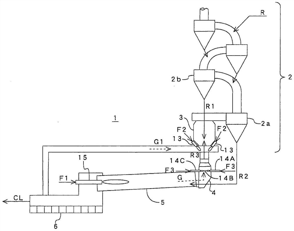
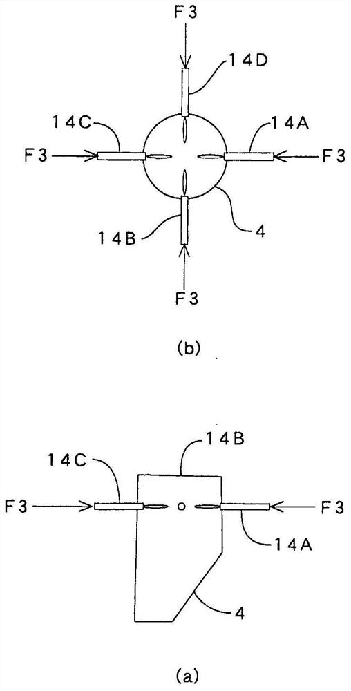
[0020] figure 1 with figure 2 One embodiment of the cement burning device according to the present invention is shown. The cement burning device 1 is composed of a preheater 2 for preheating cement raw material (hereinafter referred to as "raw material") R, and blown from a burner 13 of a calciner. The incoming fuel F2 will come from the pre-burning furnace 3 of the raw material R1 of the cyclone 2b of the third stage from the top of the pre-heater 2, and the fuel F1 blown from the main burner 15 will be used to use the fuel F1 blown in from the pre-heater 2 The cement kiln 5 for firing the raw material R2 of the lower cyclone 2a, the clinker cooler 6 for cooling the cement clinker fired in the cement kiln 5, and the four combustion chambers for denitrification installed at the kiln tail 4 of the cement kiln 5 devices 14 (14A to 14D) and the like. In addition, except the denitrification burner 14, the structure of the preheater 2, the calciner 3, the cement kiln 5, the clin...


PUM


Abstract

[Problem] To reduce the NOx concentration in cement kiln exhaust gas. [Solution] A cement firing device 1 is equipped with a plurality of denitrification burners 14 (14A to 14D) which are provided atthe kiln inlet 4 of a cement kiln 5 and inject, into the kiln inlet, combustion air and a fuel F3 in an overall amount of between 50% and 100% of the fuel F2 being burned in a precalcination oven 3 installed on the cement kiln. Increasing the fuel injected into the kiln inlet increases the amount of reducing agent, while causing the influence from the kiln inlet O2 to be mostly lost, allowing theNOx concentration in the kiln exhaust gas to be reduced further. The provision of a plurality of denitrification burners allows for a reduction in the injection amount per denitrification burner, theprevention of coating adhesion and fuel-to-fuel collision, and a higher probability of the injected fuel mixing with the kiln exhaust gas flowing in the kiln inlet and colliding with the NOx in the kiln exhaust gas. Providing the plurality of denitrification burners in the same horizontal plane further increases the probability of colliding with the NOx in the kiln exhaust gas.

Description

technical field [0001] The present invention relates to a technique for reducing the concentration of nitrogen oxides (hereinafter referred to as "NOx") in combustion gas discharged from a cement kiln. Background technique [0002] The exhaust gas from the cement kiln contains NOx originating from the high-temperature region of the firing zone. When the concentration of NOx is high, denitration agents such as urea and ammonia are added, and it is generated by combustion in the pre-fired furnace (Ka-fired furnace). The reduction effect reduces the NOx concentration. However, in the method of using urea as a denitration agent, since the price of urea is high, the running cost is high. In addition, only by adding urea, the denitrification efficiency is low, and the residual ammonia that does not react with NOx may be directly discharged out of the system. [0003] Therefore, the present applicant proposes a technique of reducing NOx in the cement kiln exhaust gas in a low-oxy...

Claims


Application Information

Patent Timeline
Patent Type & Authority Applications(China)
IPC IPC(8): C04B7/44B01D53/56B01D53/76
CPCC04B7/36C04B7/44C04B7/43B01D53/76B01D53/56Y02P40/125C04B7/436C04B7/364
Inventor 山本泰史广濑敏章
Owner TAIHEIYO ENG
Learn More