Feeding and taking bracket for ultrasonic heat sealing machine

A heat sealing machine and ultrasonic technology, which is applied in the field of feeding and retrieving brackets for ultrasonic heat sealing machines, can solve the problems of increasing the workload of operators, the inability to adjust the height, fabric wrinkles, etc., so as to facilitate the wide promotion of the market and avoid deviation. , to ensure the effect of heat sealing standards

Active Publication Date: 2021-04-06
南京金腾智能科技有限公司
View PDF23 Cites 0 Cited by
  • Summary
  • Abstract
  • Description
  • Claims
  • Application Information

AI Technical Summary

Problems solved by technology

[0003]The traditional feeding and unloading bracket for ultrasonic heat sealing machine is often just a flat panel, which is completely relied on by the operator when the ultrasonic heat sealing machine heats textiles , often in the process of heat sealing, the fabric is wrinkled due to the shaking of the operator, which easily leads to the deviation of the heat sealing position, which not only increases the workload of the operator, but also affects the heat sealing effect of the finished product. Most ultrasonic heat sealing machines on the market There will be a penetration hole on the panel of the feeding and retrieving bracket, which is convenient for the penetration of ultrasonic waves when heat-sealing products. However, some products often have requirements for flatness. Due to the difference in force at the penetration hole during heat-sealing work , will lead to changes in the flatness of the product, so that the final product specification of the product cannot be reached, which limits the practicability of the bracket and is not conducive to the wide promotion of the market. Most of the feeding and retrieving brackets for ultrasonic heat sealing machines cannot be adjusted. High and low, not conducive to the use of different operators

Method used


Image

  • Feeding and taking bracket for ultrasonic heat sealing machine
  • Feeding and taking bracket for ultrasonic heat sealing machine
  • Feeding and taking bracket for ultrasonic heat sealing machine

Examples


Embodiment Construction

[0022] The following will clearly and completely describe the technical solutions in the embodiments of the present invention with reference to the accompanying drawings in the embodiments of the present invention. Obviously, the described embodiments are only some, not all, embodiments of the present invention. Based on the embodiments of the present invention, all other embodiments obtained by persons of ordinary skill in the art without making creative efforts belong to the protection scope of the present invention.

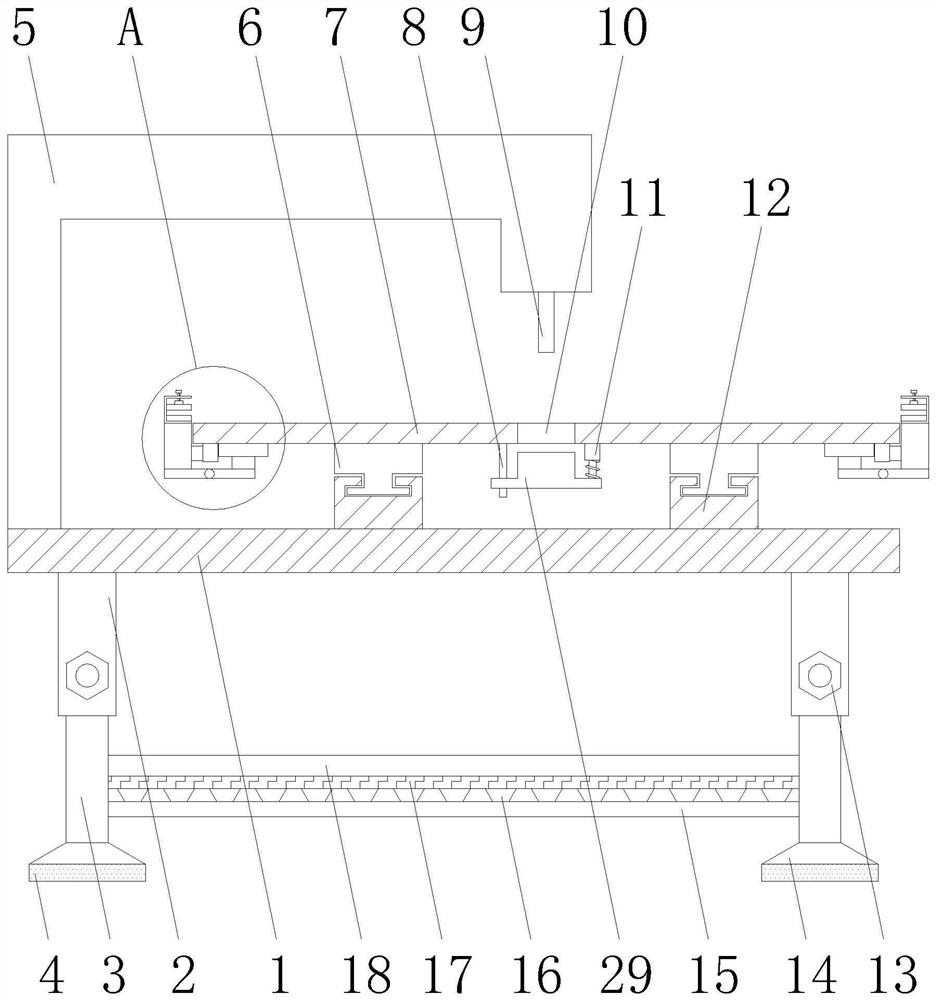
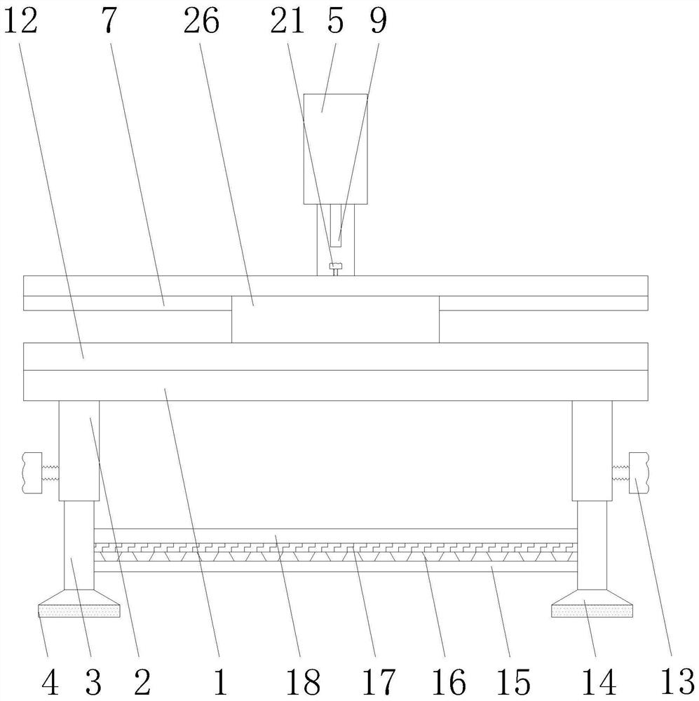
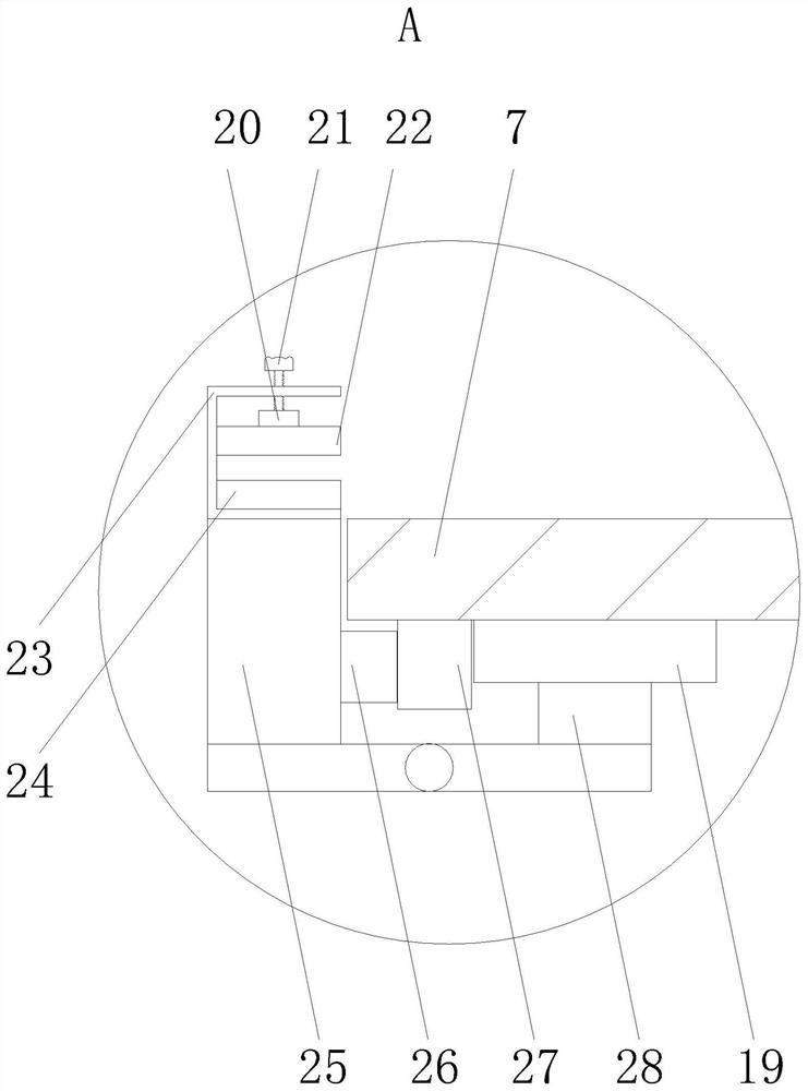
[0023] see Figure 1-3, the present invention provides a technical solution: a feeding and retrieving bracket for an ultrasonic heat sealing machine, including a support plate 1 and two movable clamping blocks 22, two first slide rails 12 are welded on the top of the support plate 1, two The inner rails of the first slide rail 12 are all slidably connected with the first sliding block 6, the tops of the two first sliding blocks 6 are jointly welded with a brac...


PUM


Abstract

The invention relates to the technical field of bracket mechanisms, and discloses a feeding and taking bracket for an ultrasonic heat sealing machine. The feeding and taking bracket for the ultrasonic heat sealing machine comprises a supporting plate and two movable clamping blocks, wherein two first sliding rails are welded to the top of the supporting plate, and first sliding blocks are slidably connected to inner rails of the two first sliding rails separately; and a bracket plate is jointly welded to the tops of the two first sliding blocks, two second sliding rails are welded to the bottom of the bracket plate, and second sliding blocks are slidably connected to inner rails of the two second sliding rails. According to the invention, through arrangement for a clamping mechanism and a moving mechanism, the deviation of a heat sealing position is avoided, the workload of workers is reduced, and the effect of ensuring the heat sealing standard of finished products is achieved; through arrangement for a guide rod, a telescopic rod and a filling block, wider practicability of the bracket is achieved, and the effect of facilitating wide market popularization is realized; and through arrangement for a limiting mechanism, height adjusting work for the bracket is completed, and the effect of facilitating use of different operators can be realized.

Description

technical field [0001] The invention relates to the technical field of bracket mechanisms, in particular to a feeding and retrieving bracket for an ultrasonic heat sealing machine. Background technique [0002] Ultrasonic heat sealing machine, also known as: ultrasonic lace machine, ultrasonic sewing machine, ultrasonic embossing machine, ultrasonic embossing machine, ultrasonic trimming machine, ultrasonic composite machine, ultrasonic pressing machine, ultrasonic Velcro slitting machine, ultrasonic yarn Mesh welding machine, ultrasonic semi-automatic non-woven bag making machine, the working principle is to use high-frequency oscillation to transmit sound waves from the welding head to the welding surface of the work object, which instantly causes friction between the work object molecules and reaches the melting point of the plastic, thereby completing the rapid dissolution of solid materials , complete welding. The strength of the joining point is close to that of a who...

Claims


Application Information

Patent Timeline
IPC IPC(8): B29C65/08B29C65/78
CPCB29C65/08B29C65/7802B29C65/7841B29C65/7858
Inventor 许世金
Owner 南京金腾智能科技有限公司
Why Eureka
Try Eureka