Mask plate and mask plate assembly

A mask plate and component technology, which is applied in metal material coating process, vacuum evaporation coating, coating, etc., can solve the problems affecting the evaporation accuracy and the position deviation of the opening, so as to improve the evaporation accuracy and prevent The effect of shifting

Pending Publication Date: 2020-11-13
HEFEI VISIONOX TECH CO LTD
View PDF13 Cites 3 Cited by
  • Summary
  • Abstract
  • Description
  • Claims
  • Application Information

AI Technical Summary

Problems solved by technology

[0004] However, during the welding process, wrinkles are formed in the welding area, and these wrinkles will extend into

Method used


Image

  • Mask plate and mask plate assembly
  • Mask plate and mask plate assembly
  • Mask plate and mask plate assembly

Examples


Example Embodiment

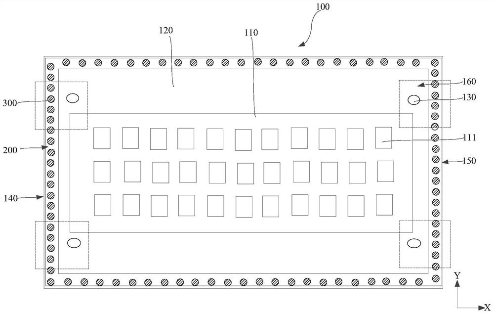
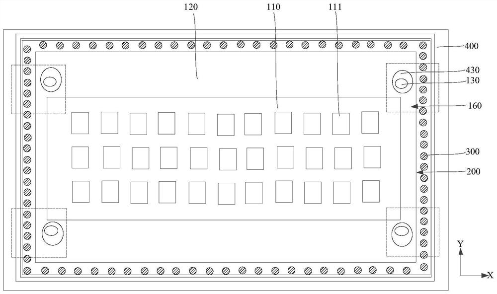
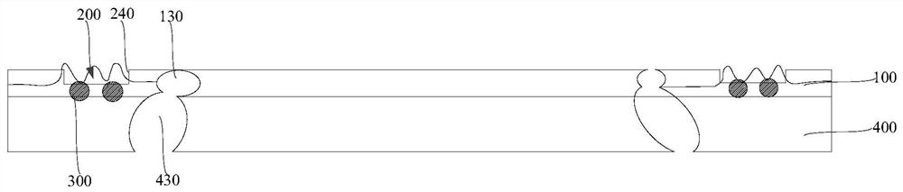
[0059] The inventor of the present application discovered in the actual work process that when the mask is placed on the frame by clamping jaws and the mask is welded to the frame by laser welding, stress will be formed inside the mask. The stress is concentrated in some areas of the mask, for example, when the alignment holes are located, these areas will be wrinkled. In the subsequent evaporation and alignment process, the magnetic adsorption will expand the above-mentioned wrinkles and reduce the above-mentioned wrinkles. Extending to the opening area of ​​the mask causes the position of the opening area to be shifted, reducing the position accuracy of vapor deposition (PAA), and then causing the pixels of the vapor-deposited OLED device to shift, which affects the normal display of the OLED device.

[0060] In view of the foregoing technical problems, embodiments of the present invention provide a mask and a mask assembly. By providing a barrier groove on the mask, when the wr...


PUM


Abstract

The invention provides a mask plate and a mask plate assembly, and relates to the technical field of display. The mask plate comprises an open area and a welding area arranged around the open area, and a stop groove is arranged outside the open area. When the mask plate is welded to a framework, wrinkles can be formed on the mask plate. The stop groove is arranged on the mask plate and can stop transmission of wrinkles, wrinkles are prevented from being transmitted into the open area of the mask plate, then the position of the open area is prevented from deviating, and evaporation precision isimproved.

Description

technical field [0001] The invention relates to the field of display technology, in particular to a mask plate and a mask plate assembly. Background technique [0002] The film layer structure in an Organic Light-Emitting Diode (OLED for short) usually needs to be formed by vapor deposition using a mask assembly (MFA). [0003] The mask plate assembly usually includes a frame and a mask plate, wherein the mask plate includes an opening area and a welding area arranged around the opening area, and alignment holes are arranged in the welding area; when forming the mask plate assembly, it is usually necessary to first The mask plate is placed on the frame, and the alignment holes on the mask plate are aligned with the alignment holes on the frame, and then the welding area of ​​the mask plate is welded on the frame. [0004] However, during the welding process, wrinkles are formed in the welding area, and these wrinkles will extend into the opening area, causing the position o...

Claims


Application Information

Patent Timeline
IPC IPC(8): C23C14/04C23C14/24
CPCC23C14/042C23C14/24
Inventor 王恩霞孙琳李世泰李慧李伟丽刘明星甘帅燕
Owner HEFEI VISIONOX TECH CO LTD
Why Eureka
Try Eureka