
Rope drive device for pod deformation

A driving device and pod technology, which is applied in the direction of hoisting device, military equipment configuration, equipment for loading and unloading goods, etc. To achieve one-way flexibility and other issues, to achieve the effect of recycling safety, good fixing and winding, and reducing quality

Active Publication Date: 2021-11-05
INST OF MECHANICS CHINESE ACAD OF SCI
View PDF5 Cites 0 Cited by
  • Summary
  • Abstract
  • Description
  • Claims
  • Application Information

AI Technical Summary

Problems solved by technology

[0005] However, for some special flight scenarios where electric actuators cannot complete specific tasks, it is necessary to use lightweight transmission, long-distance transmission, synchronous transmission, and flexible transmission. Range body deformation, the transmission mechanism is difficult to achieve long-distance transmission, synchronous transmission, and the increase in stroke angle has brought about a substantial increase in mass. At the same time, the traditional transmission method is difficult to achieve one-way flexibility, which cannot meet the one-way deformation requirements of the cabin landing buffer
[0006] At present, most of the various winch systems are single-rope or double-rope towing, and there is little research on the multi-rope synchronous retractable winch system, especially the multi-rope synchronous drive winch system in the pod. It is necessary to use a multi-rope synchronous retractable winch system to complete long-distance, large-scale, and lightweight synchronous transmission. Therefore, a multi-rope synchronous retractable winch system is urgently needed to complete the simultaneous deformation of the deformable pod body and the one-way flexible task of landing buffer

Method used


Image

  • Rope drive device for pod deformation
  • Rope drive device for pod deformation
  • Rope drive device for pod deformation

Examples


Embodiment 1

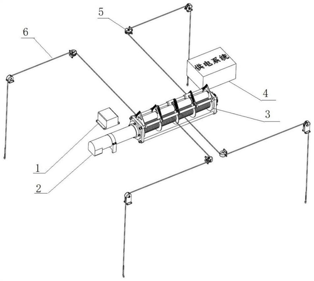
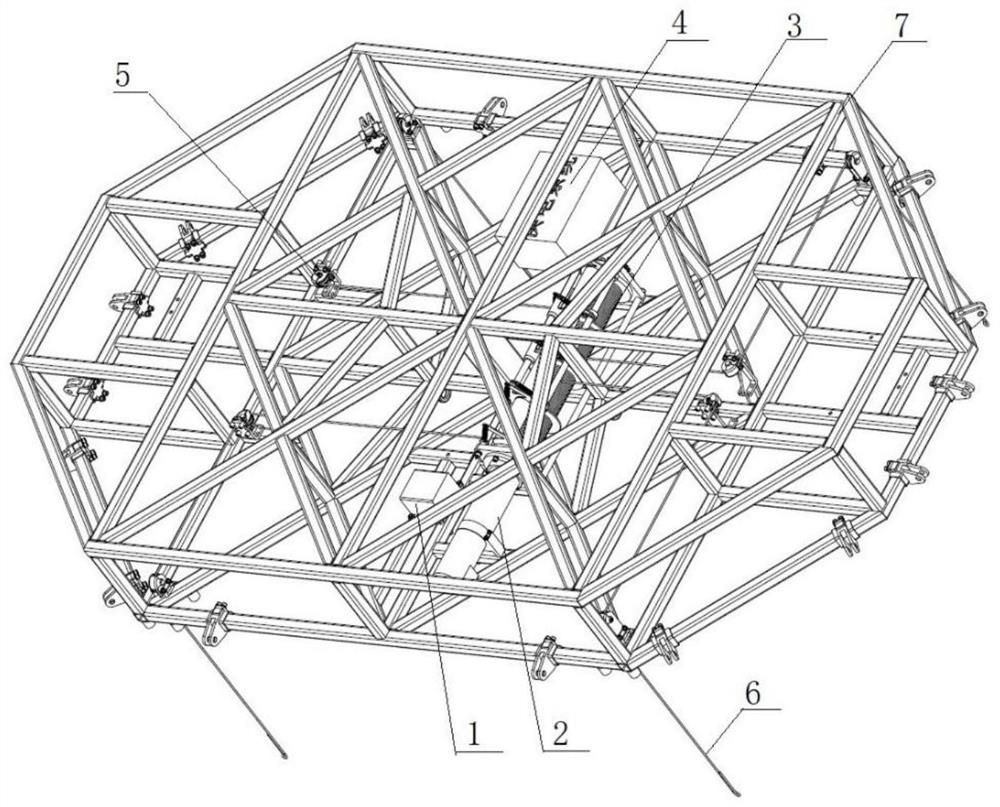
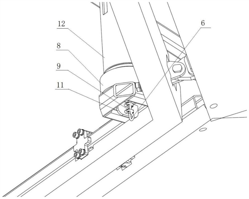
[0038] The embodiment of the present invention relates to a tether drive system for pod deformation, such as figure 1 , figure 2 , image 3 with Figure 7 As shown, a rope drive system for pod deformation, including control system 1, motor drive system (including power-off brake) 2, four-row electric synchronous winch system 3, power supply system 4, pulley direction change system 5, wire rope It is composed of seven parts such as 6 and the fixed frame 7 of the electric load compartment of the pod. Among them, the motor drive system (including power-off brake) 2 is fixedly installed on the flange of the four-row electric synchronous winch system 3 through bolts, and one end of the steel wire rope system 6 is fixedly installed on the end of the four-row electric synchronous winch system 3, and the other end is wound around the four-row electric synchronous winch system. Pass four rows of rollers 32, then pass through the pulley direction changing system 5, then pass through...


PUM


Abstract

The invention belongs to the technical field of pod auxiliary equipment. Based on the shortcomings of existing electric actuators and other actuators and single- and double-rope retractable winch systems used in the deformation of deformable pods, the invention discloses a pod deformation The rope driving device, the control system, the motor drive system, the four-row electric synchronous winch system, the power supply system, and the pulley direction changing system are respectively fixedly installed on the corresponding positions on the fixed frame of the electric load compartment of the pod, and the motor drive system is fixedly installed on the On the four-row electric synchronous winch system, one end of the wire rope is fixedly installed at the end of the four-row electric synchronous winch system, and the other end goes around the four-row rollers of the four-row electric synchronous winch system, then passes through the pulley direction change system, and then passes through the four-row electric synchronous winch system. The inside of the synchronous shock absorber of the pod is finally fixed on the bottom frame of the pod. It ensures the stable deformation of the cabin and reduces the mass of the drive system; it has wide applicability and high deformation safety; it ensures that the wire rope will not be messed up during the retraction process; it can achieve good fixation and winding of multiple winches, and the structure is simple and compact.

Description

technical field [0001] The invention belongs to the technical field of pod auxiliary equipment, and in particular relates to a rope driving device for pod deformation. Background technique [0002] The pod refers to a streamlined nacelle section that is installed with certain airborne equipment or weapons and hangs under the fuselage or wing. With the development of aviation technology, airborne pod technology has also made great progress. Generally speaking, airborne pods can be divided into: weapon pods (including aircraft gun pods, aviation rocket pods), reconnaissance pods, fire control pods, and logistics auxiliary pods (refueling pods). [0003] At present, there are few studies on aerostat launch pods in the world, especially there is no precedent for aerostat launch pods with deformable bodies. [0004] At present, various linear electric actuators, steering gears and other actuators are widely used in the aerospace field, and can complete various tasks such as cha...

Claims


Application Information

Patent Timeline
Patent Type & Authority Patents(China)
IPC IPC(8): B66D1/74B66D1/26B66D1/12B66D1/36B66D1/30B66C13/06B66C13/08B64D7/00B64D9/00
CPCB64D7/00B64D9/00B66C13/06B66C13/08B66D1/36B66D1/7405B66D1/7447
Inventor 王福德李文皓彭青杨磊李腾
Owner INST OF MECHANICS CHINESE ACAD OF SCI
Learn More