Intelligent gutter snow melting system
A technology for melting snow and gutters, which is applied to roofing, buildings, building structures, etc., can solve problems such as waste of electric energy, achieve the effects of avoiding power consumption, realizing intelligent operation, and reducing labor costs
- Summary
- Abstract
- Description
- Claims
- Application Information
AI Technical Summary
Problems solved by technology
Method used
Image
Examples
Embodiment 1
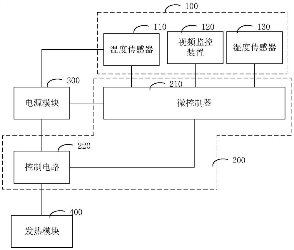
[0023] figure 1 Shown is a schematic structural diagram of an intelligent gutter snow melting system provided by an embodiment of the present invention, as figure 1 As shown, the intelligent gutter snow melting system provided in this embodiment specifically includes:
[0024] Environmental monitoring module 100, intelligent control module 200, power module 300 and heating module 400;
[0025] The power module 300 is connected to the environment monitoring module 100, the intelligent control module 200 and the heating module 400, and is used to provide the environment monitoring module 100, the intelligent control module 200 and the heating module 400 electric energy;
[0026] The heating module 400 is used to convert the electric energy into heat energy for melting ice and snow;
[0027] The environmental monitoring module 100 includes a temperature sensor 110 and a video monitoring device 120, the temperature sensor 110 is used to collect the current temperature data of t...
Embodiment 2
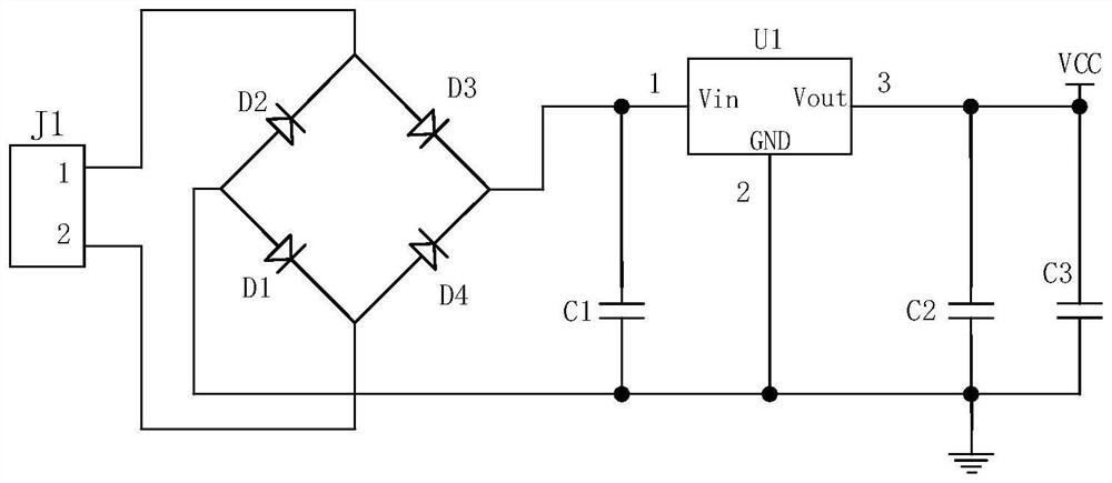
[0037] figure 2 Shown is a schematic circuit diagram of a power supply module provided by an embodiment of the present invention, such as figure 2 As shown, the power module 300 provided in this embodiment specifically includes:
[0038] Power socket J1, the first end of the power socket J1 is connected to an external AC power when in use;
[0039] A rectification circuit, the first input end of the rectification circuit is connected to the second end of the power socket J1, the second input end of the rectification circuit is connected to the third end of the power socket J1, for connecting the Convert external alternating current to direct current;
[0040] A voltage stabilizing circuit, the input end of the voltage stabilizing circuit is connected to the output end of the rectification circuit, and the output end of the voltage stabilizing circuit is the output end of the power module.
[0041] In an embodiment of the present invention, the power supply module 300 furt...
Embodiment 3
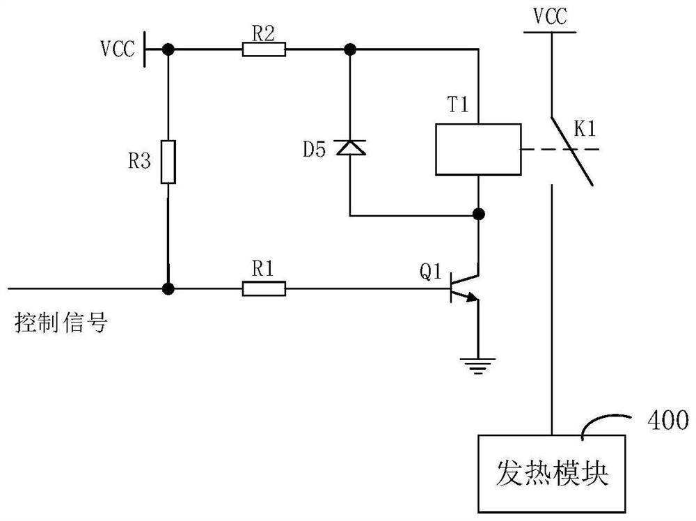
[0046] image 3 Shown is a schematic circuit diagram of a control circuit provided by an embodiment of the present invention; image 3 As shown, the control circuit 220 includes:
[0047] A first resistor R1, the first end of the first resistor R1 is connected to the output end of the microcontroller 210;
[0048] A triode Q1, the base of the triode Q1 is connected to the second end of the first resistor R1, and the emitter of the triode Q1 is grounded;
[0049] A relay, the first end of the coil T1 of the relay is connected to the collector of the triode Q1, the first end of the normally open switch K1 of the relay is connected to the output end of the power module 300, the normally open switch of the relay The second end of K1 is connected to the heating module 400;
[0050] The second resistor R2, the first end of the second resistor R2 is connected to the second end of the coil T1 of the relay, and the second end of the second resistor R2 is connected to the output end ...
PUM
 Abstract
Description
Claims
Application Information
 - R&D
- Intellectual Property
- Life Sciences
- Materials
- Tech Scout
- Unparalleled Data Quality
- Higher Quality Content
- 60% Fewer Hallucinations
Browse by: Latest US Patents, China's latest patents, Technical Efficacy Thesaurus, Application Domain, Technology Topic, Popular Technical Reports.
© 2025 PatSnap. All rights reserved.Legal|Privacy policy|Modern Slavery Act Transparency Statement|Sitemap|About US| Contact US: help@patsnap.com


