Wave energy collection device driven by dual-rotation of single gear ring

A collection device, wave energy technology, applied in ocean energy power generation, engine components, machines/engines, etc., can solve the instability of wave energy, the negative impact of collecting wave energy, and reduce the three-dimensionality, randomness and inconstancy of waves Wave energy collection and other issues, to achieve the effect of improving collection efficiency, small energy loss, and strong corrosion resistance

Active Publication Date: 2021-04-06
王兴奎 +1
View PDF7 Cites 0 Cited by
  • Summary
  • Abstract
  • Description
  • Claims
  • Application Information

AI Technical Summary

Problems solved by technology

These characteristics have a great negative impact on the collection of wave energy, making the design of a single wave energy collection device extremely complicated, and the collected wave energy is also very unstable
The research and development of various existing wave energy harvesting devices are mostly single devices, all of which are committed to reducing the adverse effects of the three-dimensionality, randomness and inconsistency of waves on wave energy collection

Method used


Image

  • Wave energy collection device driven by dual-rotation of single gear ring
  • Wave energy collection device driven by dual-rotation of single gear ring
  • Wave energy collection device driven by dual-rotation of single gear ring

Examples


Embodiment Construction

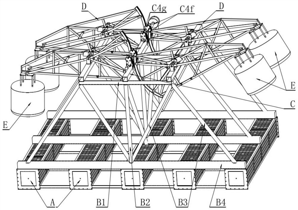
[0028] The following will be combined with figure 1 ~ attached Figure 8 and Embodiments A single-geared double-rotation-driven wave energy collection device of the present invention will be described in detail.

[0029] figure 1 It is a schematic diagram of the overall structure of the embodiment of the present invention, including a bottom floating body A, a middle frame B, an upper platform C, a plurality of rotating frames D installed on the upper platform C, and a plurality of floating balls E installed at the ends of each rotating frame D respectively . A middle frame B is erected on the upper plane of the floating body A at the bottom, and an upper platform C is installed on it to form a floating platform. Each rotating frame D and the floating ball E at its end constitute a wave energy collecting member. In order to meet the requirements of standardized and modular processing, and to facilitate transportation, including but not limited to the use of four wave energ...


PUM


Abstract

The invention relates to a wave energy collection device driven by dual-rotation of a single gear ring, and belongs to the field of green renewable energy based on utilization of wave energy. The wave energy collection device comprises a bottom floating body, a middle framework, an upper platform, rotary frames and floating balls, wherein the floating balls are suspended under one end of each of the rotary frames while the other ends of the rotary frames are provided with arc gear rings; the circle centers of the arc gear rings are fixedly mounted on the upper platform by using a bearing; the arc gear rings are engaged with a main ratchet of a power shaft; through a steering wheel, an outer gear ring of an auxiliary ratchet and an outer gear ring of the main ratchet mutually rotate oppositely, and the outer gear rings of the ratchets are rotated clockwise to output power, and are rotated anticlockwise to be rotated in an idle state; when the floating balls ascend, the main ratchet is rotated clockwise to output the power, and the auxiliary ratchet is rotated anticlockwise to be rotated in the idle state; and when the floating balls descend, the main ratchet is rotated in the idle state, and the auxiliary ratchet is rotated clockwise to output the power, so that the power shaft is driven by dual-rotation of the single gear ring to apply work; and through a moment manner, vertical and horizontal acting force of wave fluctuation can be collected. By adopting the device disclosed by the invention, the natural attributes, i.e., three-dimension, random and inconstancy, of the natural wave are fully utilized, and collection of wave energy is realized.

Description

technical field [0001] The invention belongs to the field of green renewable energy utilizing wave energy, and in particular relates to a wave energy collection device with single gear ring and double rotation drive. Background technique [0002] Wave energy refers to the energy of waves on the water surface. It is widely distributed in oceans, lakes, and reservoirs, has high energy density, and is easy to use on a large scale. It is a typical clean, non-polluting, and rapidly developing green renewable energy. my country is a big ocean country with rich ocean energy resources and broad prospects for development. Many islands in my country basically do not have grid power supply, and the production and life of the residents on the islands are relatively backward. The difficulty of power supply restricts their economic development; especially the offshore working platforms and Xisha and Nansha islands far away from the mainland have more urgent demand for power. , so the rese...

Claims


Application Information

Patent Timeline
Patent Type & Authority Applications(China)
IPC IPC(8): F03B13/16F03B11/06
CPCF03B13/16F03B11/06Y02E10/20Y02E10/30
Inventor 王兴奎黄泽俊
Owner 王兴奎
Why Eureka
Try Eureka