Oil fume suction device

A technology for absorbing oil fume and oil fume box is applied in the field of range hoods, which can solve the problems of small inhalation of oil fume, poor fume collection effect, oil pollution, etc., and achieves the advantages of increasing the cooling contact area, improving the air outlet effect, and increasing the speed of oil fume. Effect

Active Publication Date: 2021-04-06
XI AN JIAOTONG UNIV
View PDF5 Cites 0 Cited by
  • Summary
  • Abstract
  • Description
  • Claims
  • Application Information

AI Technical Summary

Problems solved by technology

Traditional range hoods use multi-blade centrifugal fans to directly inhale smoke exhaust. There is only one oil suction port located below the main body. At the same time, there is mostly a single multi-blade centrifugal fan inside. The oil fume suction is small, the wind pressure is small, and the smoke collection effect is excellent. Poor, it is easy to cause oil fumes to spread and pollute in the kitchen, seriously affecting the health of cooks
[0003] At the same time, the traditional oil fume separation of range hoods mostly adopts fan impeller centrifugal treatment and filter screen to block adsorption. The grease separation effect is not significant, and it is easy to cause a large amount of oil fume to be discharged into the atmosphere, causing oil pollution in the atmosphere and polluting the environment.

Method used


Image

  • Oil fume suction device
  • Oil fume suction device
  • Oil fume suction device

Examples


Embodiment Construction

[0036] The present invention is described in further detail below in conjunction with accompanying drawing:

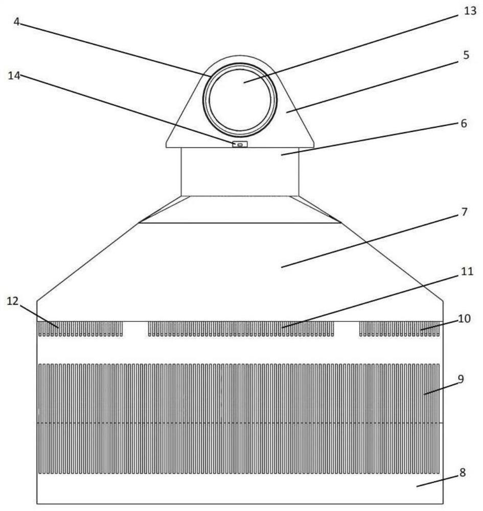
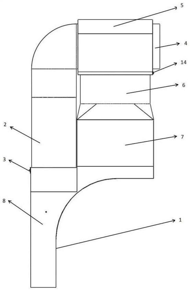
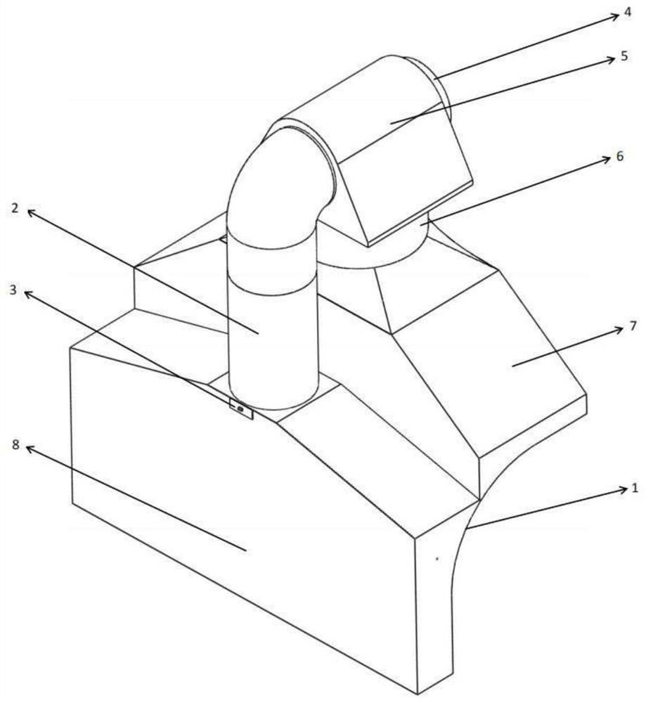
[0037] Such as Figure 1 to Figure 10As shown, a kind of oil suction fume device comprises jet side oil suction flue 2, jet flow drainage chamber 5, fan side air outlet air duct 6, fan side oil suction fume box 7 and jet side oil suction fume box 8, fan side oil suction fume box 7 It is arranged on the upper end of the jet side oil suction box 8 and the jet side oil suction box 8 is arranged on one side of the fan side oil suction box 7, and the fan side oil suction box 7 is connected with the jet side oil suction box 8, that is, the fan side oil suction box 7 and The jet side oil suction box 8 can adopt the same shell 1, the lower end of the fan side oil suction box 7 is provided with an air inlet, the side wall of the jet side oil suction box 8 is provided with a jet chamber oil suction port 9, and the jet chamber oil suction port 9 There is a guide vane ring 15, an...


PUM


Abstract

The invention discloses an oil fume suction device. A jet flow side oil fume suction box is arranged on one side of the lower end of a fan side oil fume suction box, the upper end of the jet flow side oil fume suction box and the upper end of the fan side oil fume suction box are communicated with a jet flow diversion chamber, and a spiral air deflector is arranged in a jet flow side oil fume suction channel; in this way, the cooling contact area between the oil fume and the wall surface of the air deflector is increased, so that small oil drops in the oil fume are attached to the wall surface of the spiral air deflector, and grease in the oil fume can be effectively separated; meanwhile, the upper end of the fan side oil fume suction box is communicated with a fan side outer air outlet duct through a multi-wing centrifugal fan air outlet section, an axial flow wind wheel is arranged at the air outlet end of the multi-wing centrifugal fan air outlet section, negative pressure is formed in a fan side inner air outlet duct through the axial flow wind wheel, and then the oil fume suction amount is increased; meanwhile, exhausted high-speed airflow enters the space between the fan side outer air outlet duct and the fan side inner air outlet duct, the airflow speed of airflow exhausted by a fan side left oil fume suction chamber and a fan side right oil fume suction chamber is low relative to the airflow speed of the fan side inner air outlet duct, and then the speed for the oil fume to enter the fan side inner air outlet duct is increased.

Description

technical field [0001] The invention relates to the field of range hoods, in particular to a range hood device. Background technique [0002] Green, healthy, and environmental protection have become a global consensus. Range hood is one of the most commonly used kitchen appliances, and its development is also based on the basic principles of green, health and environmental protection. Traditional range hoods use multi-blade centrifugal fans to directly inhale smoke exhaust. There is only one oil suction port located below the main body. At the same time, there is mostly a single multi-blade centrifugal fan inside. The oil fume suction is small, the wind pressure is small, and the smoke collection effect is excellent. Poor, it is easy to cause oil fumes to spread and pollute in the kitchen, seriously affecting the health of cooks. [0003] At the same time, the traditional oil fume separation of range hoods mostly adopts fan impeller centrifugal treatment and filter screen ...

Claims


Application Information

Patent Timeline
Patent Type & Authority Applications(China)
IPC IPC(8): F24C15/20
CPCF24C15/2035
Inventor 刘小民王加浩席光田晨晔
Owner XI AN JIAOTONG UNIV
Why Eureka
Try Eureka