A Deformable Mirror Unit with Deformation Compensation and a Discrete Deformable Mirror System
A deformation compensation, deformation mirror technology, applied in the optical field, can solve the problems of reducing beam quality, image degradation, uneven distribution of atmospheric refractive index, etc., to achieve the effects of accurate signal, improved heat dissipation performance, and reduced temperature
Active Publication Date: 2022-08-05
HANGZHOU DIANZI UNIV
View PDF7 Cites 0 Cited by
- Summary
- Abstract
- Description
- Claims
- Application Information
AI Technical Summary
Problems solved by technology
Random changes in the refractive index produce significant inhomogeneity in the distribution of the atmospheric refractive index on a large scale, resulting in changes in the wavefront of the beam during atmospheric transmission, reducing the quality of the beam and causing image degradation
Method used
View moreImage
Smart ImageViewing Examples
Examples
Embodiment 2
[0041] A discrete deformable mirror system includes deformable mirror units arranged in an array; the correction and restoration of external light beams are realized through independent control of each deformable mirror unit.
Login to View More PUM
 Abstract
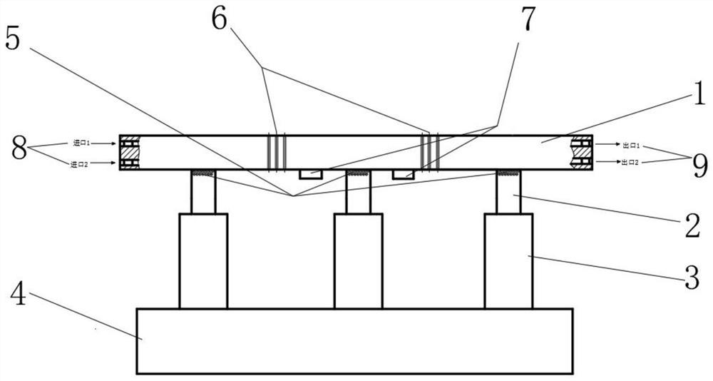
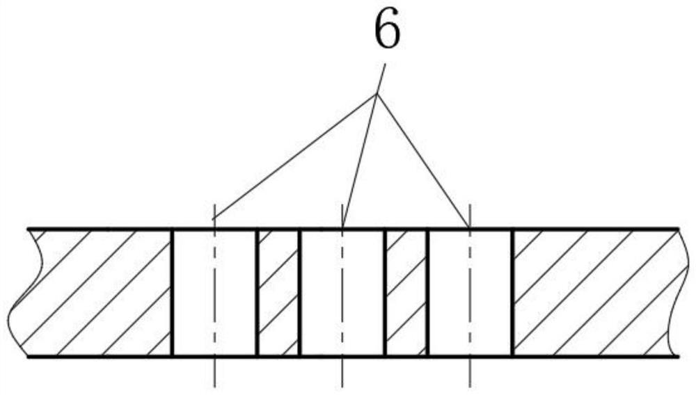
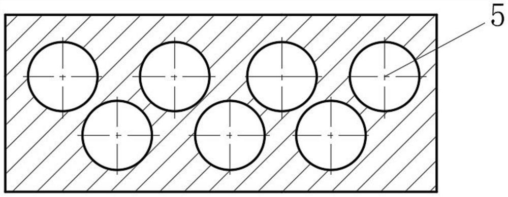
The invention discloses a deformable mirror unit with deformation compensation and a deformable mirror system. The invention discloses a deformable mirror unit with deformation compensation, which includes a single deformable lens, a pole head, a driver and a base. Multiple drives are mounted on the base. The driver can automatically expand and contract; the outer end of each driver is fixed with a pole head; the outer end face of the pole head is provided with a plurality of blind holes. The back of the single deformable lens is fixed with the outer end of each pole. The single deformable lens is provided with a plurality of through holes. The diameter of the through hole is 1 to 100 nm. In the present invention, by opening nano-scale through holes on the single deformable lens, since the diameter of the through hole is smaller than the unit gap of the deformable mirror, the through hole improves the heat dissipation performance and has almost no influence on the performance of the deformable mirror. The present invention can fully reduce the temperature of the single deformation lens by setting up a multi-layer heat dissipation flow channel which is combined with a cross-shaped flow channel and a circular flow channel.
Description
technical field [0001] The invention belongs to the technical field of optics, and in particular relates to a real-time control device for thermal deformation of a deformable mirror in an adaptive optical system. Background technique [0002] Changes in temperature in the turbulent motion of the atmosphere cause small changes in the density of the atmosphere, which in turn cause small changes in the refractive index. The random variation of the refractive index produces obvious inhomogeneity of the atmospheric refractive index distribution in the large-scale range, which leads to the change of the wavefront of the beam during the atmospheric transmission, which reduces the beam quality and causes image degradation. [0003] The adaptive optics system can effectively solve the aberration compensation problem caused by beam wavefront distortion. Its principle adopts the principle of closed-loop control system. Optical components such as stages and beamsplitters. Among them, ...
Claims
Login to View More Application Information
Patent Timeline
 Patent Type & Authority Patents(China)
IPC IPC(8): G02B26/06G02B7/18G02B7/182G01B7/16
CPCG02B26/06G02B7/1815G02B7/182G01B7/22
Inventor 李蓉吴占彬翁佳豪陆伟杨树玄张巨勇季国顺陈志平
Owner HANGZHOU DIANZI UNIV
Features
- R&D
- Intellectual Property
- Life Sciences
- Materials
- Tech Scout
- Unparalleled Data Quality
- Higher Quality Content
- 60% Fewer Hallucinations
Learn More Browse by: Latest US Patents, China's latest patents, Technical Efficacy Thesaurus, Application Domain, Technology Topic, Popular Technical Reports.
© 2025 PatSnap. All rights reserved.Legal|Privacy policy|Modern Slavery Act Transparency Statement|Sitemap|About US| Contact US: help@patsnap.com


