
Large module MOV mounting assembly with explosion-proof and pressure-relief functions for MOV chip

A technology for installing components and large modules, which is applied in the direction of resistor installation/support, varistor, resistor shell/packaging shell/potting, etc. Burning and other problems, to achieve the effect of reuse, reduce fire hazards, and prevent open flames

Active Publication Date: 2021-04-06
CHENSHUO ELECTRONICS JIUJIANG CO LTD
View PDF6 Cites 1 Cited by
  • Summary
  • Abstract
  • Description
  • Claims
  • Application Information

AI Technical Summary

Problems solved by technology

[0002] The MOV chip is a metal oxide resistor, such as a zinc oxide varistor, which is the core component of a surge protector, but when the existing zinc oxide varistor is broken down, the ceramic substrate will be perforated Melting, its center temperature will be as high as more than 1,000 degrees Celsius, and the external flame will ignite and penetrate the pressure-sensitive conventional epoxy resin encapsulation layer, causing the piezoresistor to burn and cause a fire. At the same time, the high temperature will cause the internal air pressure to increase. Burst the shell, the existing zinc oxide varistor is damaged, it is inconvenient to replace, and the installation components cannot be reused, which is wasteful

Method used


Image

  • Large module MOV mounting assembly with explosion-proof and pressure-relief functions for MOV chip
  • Large module MOV mounting assembly with explosion-proof and pressure-relief functions for MOV chip
  • Large module MOV mounting assembly with explosion-proof and pressure-relief functions for MOV chip

Examples


Embodiment Construction

[0020] The following will clearly and completely describe the technical solutions in the embodiments of the present invention with reference to the accompanying drawings in the embodiments of the present invention. Obviously, the described embodiments are only some, not all, embodiments of the present invention. Based on the embodiments of the present invention, all other embodiments obtained by persons of ordinary skill in the art without making creative efforts belong to the protection scope of the present invention.

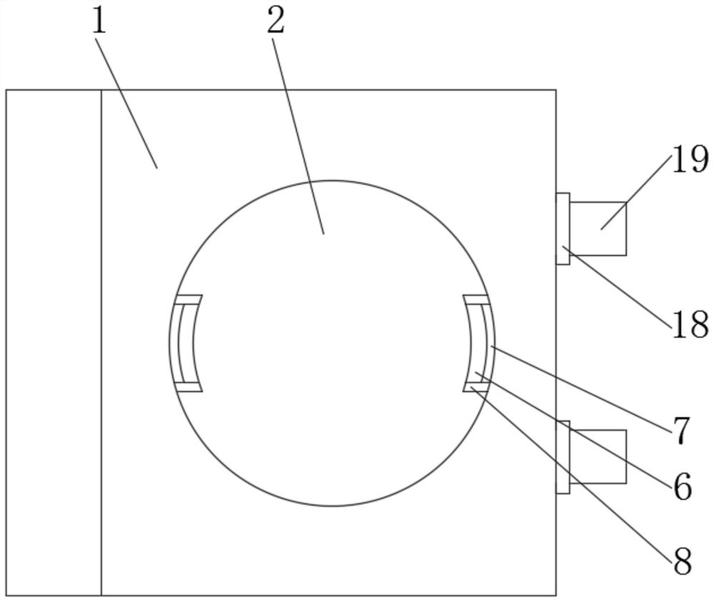
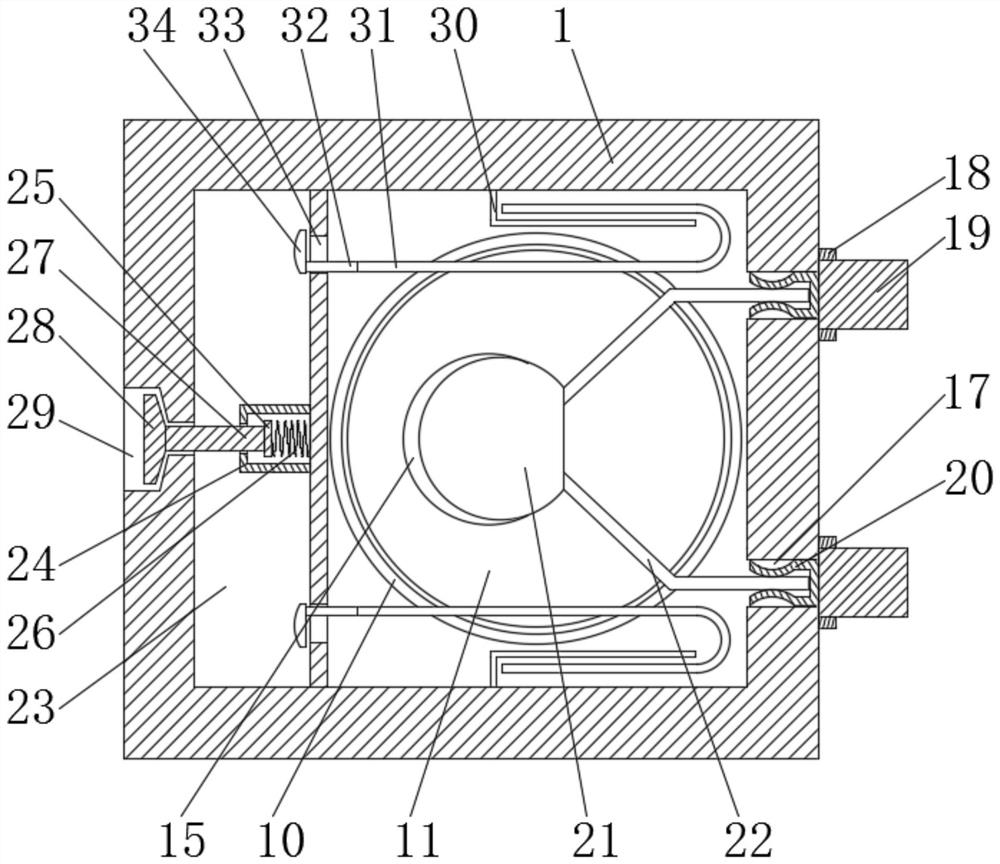
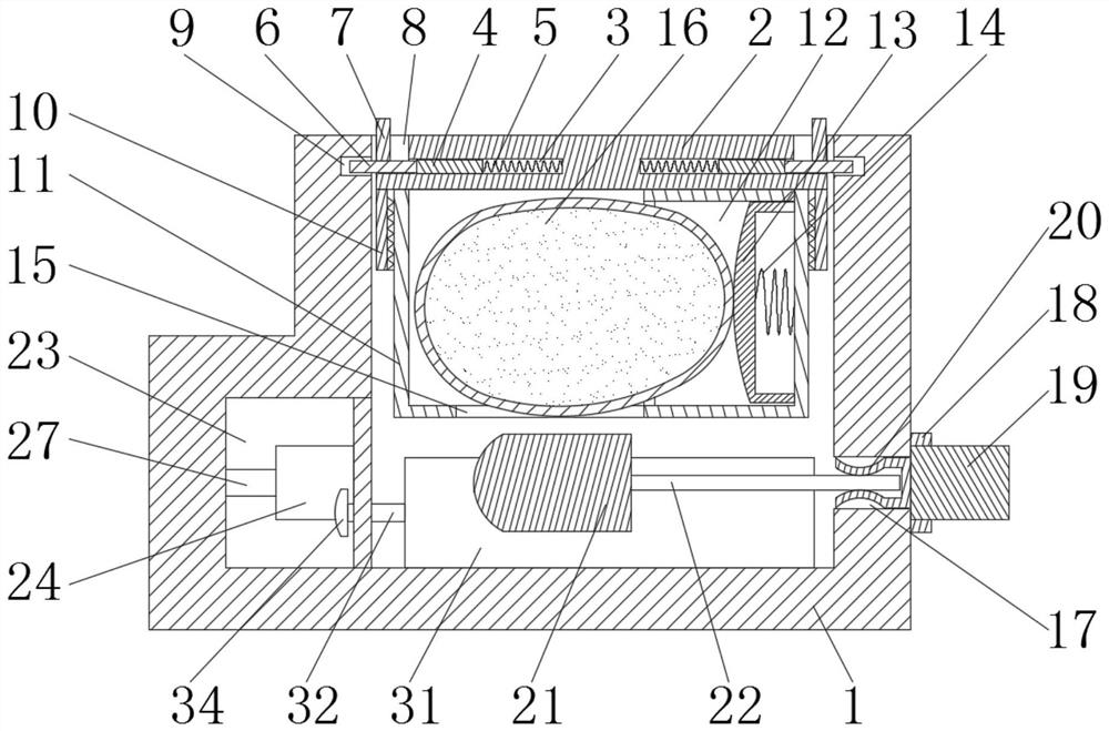
[0021] see Figure 1-6 , the present invention provides a technical solution: a large module MOV installation assembly with explosion-proof pressure relief for MOV chips, including a housing 1, a cover plate 2, a first limiting groove 3, a first limiting block 4, a first Spring 5, clamp block 6, fixed block 7, accommodation groove 8, first clamp groove 9, sleeve 10, charging box 11, second limit groove 12, top block 13, second spring 14, discharge hole 15 , m...


PUM


Abstract

The invention discloses a large module MOV mounting assembly with explosion-proof and pressure-relief functions for an MOV chip. The MOV mounting assembly comprises a shell, a cover plate, a first limiting groove, a first limiting block, a first spring, a clamping block, a fixing block, a sleeve, a charging box, a second limiting groove, a jacking block, a second spring, a discharging hole, a material bag, a through hole, an insulating ring, a plug, a clamping block, a piezoresistor body, a pin, a pressure relief chamber, a connecting rod, a piston, a pressure relief hole, a through groove and a stop block. In comparison with the existingMOV mounting assembly, a replaceable flame-retardant device is designed, open fire generated by combustion of the piezoresistor can be prevented, fire hazards are reduced, a secondary pressure relief function is designed, pressure generated by high temperature can be safely released into the environment, and meanwhile sharp gas buzzing is generated at the pressure relief hole. As the plug-in piezoresistor mounting device, after the piezoresistor is damaged, the piezoresistor can be quickly replaced, and meanwhile, the shell can be repeatedly utilized.

Description

technical field [0001] The invention relates to the technical field of MOV mounting components, in particular to a large-module MOV mounting component with explosion-proof pressure relief for MOV chips. Background technique [0002] The MOV chip is a metal oxide resistor, such as a zinc oxide varistor, which is the core component of a surge protector, but when the existing zinc oxide varistor is broken down, the ceramic substrate will be perforated Melting, its center temperature will be as high as more than 1,000 degrees Celsius, and the external flame will ignite and penetrate the pressure-sensitive conventional epoxy resin encapsulation layer, causing the piezoresistor to burn and cause a fire. At the same time, the high temperature will cause the internal air pressure to increase. If the casing is burst, the existing zinc oxide varistor is damaged, and it is inconvenient to replace, and the installation components cannot be reused, which is relatively wasteful. Content...

Claims


Application Information

Patent Timeline
Patent Type & Authority Applications(China)
IPC IPC(8): H01C7/10H01C1/14H01C1/02H01C1/01A62C3/16
CPCH01C7/10H01C1/14H01C1/02H01C1/01A62C3/16
Inventor 曾欣雯陈牧仑陈享廷
Owner CHENSHUO ELECTRONICS JIUJIANG CO LTD
Learn More