
Steel-bonded reinforcement method for grid structure

A network frame structure and steel bonding technology, which is applied in building construction, special data processing applications, building maintenance, etc., can solve the problems of steel pipe structure deformation, reinforcement parts and original rods cannot form an integral structure, etc., to extend the network frame Life expectancy, reduced impact on normal business operations, and ease of construction and operation

Pending Publication Date: 2019-10-15
SOUTHWEST JIAOTONG UNIV +1
View PDF5 Cites 1 Cited by
  • Summary
  • Abstract
  • Description
  • Claims
  • Application Information

AI Technical Summary

Problems solved by technology

[0006] In view of the above analysis, the present invention aims to provide a method for improving the safety performance of the existing space grid structure, so as to solve the need to use open flames for welding in the prior art, and the reinforcement of welding sleeves will cause obvious structural deformation of steel pipes, and the reinforcement of parts Problems such as cooperating with the original rods that cannot form an overall structure

Method used

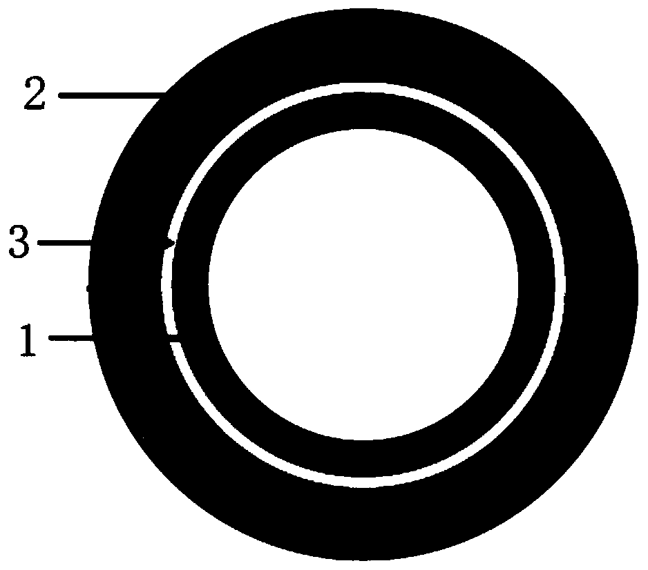
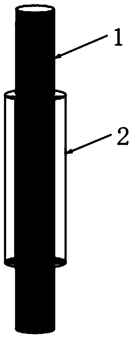
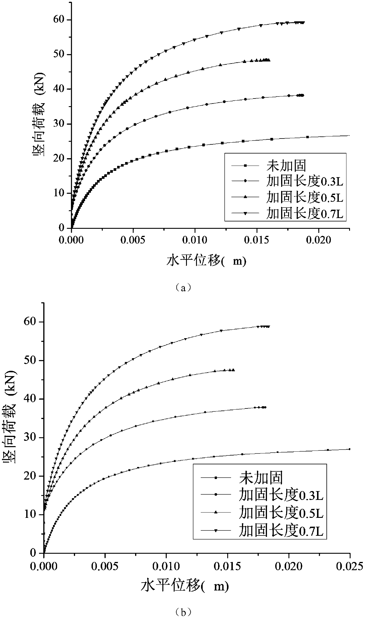

Image

  • Steel-bonded reinforcement method for grid structure
  • Steel-bonded reinforcement method for grid structure
  • Steel-bonded reinforcement method for grid structure

Examples


Embodiment Construction

[0072] A method for improving the safety performance of an existing space grid structure will be further described in detail below in conjunction with specific examples. These examples are only for the purpose of comparison and explanation, and the present invention is not limited to these examples.

[0073] A specific embodiment of the present invention, a kind of bonding steel reinforcement method for grid structure, Figure 1-Figure 2 shown, including the following steps:

[0074] S1. Confirm that the rod to be reinforced in the grid is the original rod 1; the original rod is a grid structure rod with bending deformation defects;

[0075] S2. Obtain the diameter d, deflection-span ratio, cracking degree and corrosion condition of the original rod 1;

[0076] S3. Determine the value of the damage degree S of the reinforced rod according to the deflection-span ratio, cracking degree and corrosion situation of the original rod 1;

[0077] As shown in Table 1, when the deflec...


PUM


Abstract

The invention discloses a steel-bonded reinforcement method for a grid structure and belongs to the technical field of building structure reinforcement. The steel-bonded reinforcement method for the grid structure solves the technical problems that in the prior art, open fire is needed for welding, sleeve welding type reinforcement enables a steel tube to generate obvious structural deformation, and a reinforcing portion and a raw rod piece cannot form cooperative work of an integrated structure. The steel-bonded reinforcement method for the grid structure comprises the following steps of S1,determining a to-be-reinforced rod piece in a grid frame as a raw rod piece; S2, obtaining the diameter d, the deflection-span ratio, the cracking degree and the rusting condition of the raw rod piece; S3, determining the value of the damage degree S of the to-be-reinforced rod piece according to the deflection-span ratio, the cracking degree and the rusting condition of the raw rod piece; S4, obtaining the stress ratio of the raw rod piece; S5, obtaining the length and thickness of an outer bonded steel tube according to the value of the damage degree S and the stress ratio of the rod piece;S6, symmetrically bonding the outer bonded steel tube meeting the requirements of the step S5 at the center of the raw rod piece. The steel-bonded reinforcement method for the grid structure is suitable for reinforcing the grid rod piece with a bend deformation defect.

Description

technical field [0001] The invention belongs to the technical field of building structure reinforcement, and in particular relates to a steel bonding reinforcement method for grid structures. Background technique [0002] Due to improper design and construction, changes in use requirements or applied loads, aging damage of structural components, and catastrophic effects such as fire, earthquake, and war, there are inevitably various defects and damages in steel structures. Under the action of factors such as load and environment, the microscopic and macroscopic mechanical properties of materials deteriorate, which eventually leads to macroscopic cracking or instability of steel structural members, and even engineering accidents. The failure of damaged structures is generally not caused by insufficient strength, but by instability. In order to prolong the service life of the steel structure and ensure the safe operation of the structure, it is necessary to rebuild, replace o...

Claims


Application Information

Patent Timeline
Patent Type & Authority Applications(China)
IPC IPC(8): E04G23/02G06F17/50
CPCE04G23/0218E04G23/0225G06F30/13G06F30/23
Inventor 周祎张营营赵玉帅徐俊豪赵启冲宋威吴萌付德权高振宇朱凌锋
Owner SOUTHWEST JIAOTONG UNIV
Learn More