Rotary motor rotor and motor

A technology for rotating motors and rotors, applied to synchronous machines, electric components, electrical components, etc., can solve the problems of reduced motor output torque, unreduced load torque fluctuations, and reduced air gap magnetic density, etc., to achieve improved torque density and Torque value, widening the constant power operating range, and improving the effect of field weakening speed expansion ability

Pending Publication Date: 2021-04-06
WOLONG ELECTRIC GRP CO LTD
View PDF0 Cites 0 Cited by
  • Summary
  • Abstract
  • Description
  • Claims
  • Application Information

AI Technical Summary

Problems solved by technology

[0002] At present, the traditional built-in permanent magnet rotating motor rotor punching usually adopts the design of the outer circle of the rotor as a full circle or the design of an eccentric circle for simply cutting the poles of the rotor. When the rotor is designed as a full circle, the air gap of the motor is uniform, although The overall average air-gap magnetic density is high, but the problem is that the air-gap magnetic density has a large harmonic content, the cogging positioning torque is large, and the load torque fluctuates greatly, which leads to large motor noise and vibration; simple rotor pole cutting When the eccentric circle is designed, although the air-gap flux density waveform is relatively sinusoidal, the flux density harmonics and cogging torque are greatly reduced, but the large-scale pole cutting of the outer circle of the rotor causes the magnetic pole flux leakage to increase and the air-gap flux density to decrease significantly , the saliency rate of the motor is also greatly reduced, which in turn leads to a significant reduction in the output torque of the motor, and especially for the motor with concentrated windings, the fluctuation of the load torque cannot be reduced, and the noise and vibration of the motor are still large

Method used


Image

  • Rotary motor rotor and motor
  • Rotary motor rotor and motor

Examples


Embodiment Construction

[0018] The technical solution of the present invention will be further described in detail below in conjunction with the accompanying drawings.

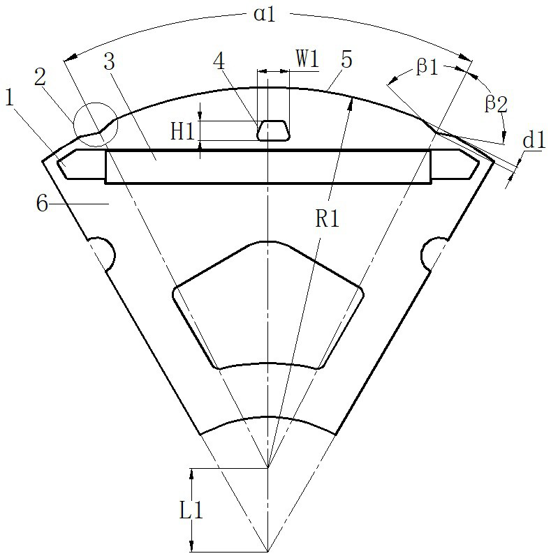
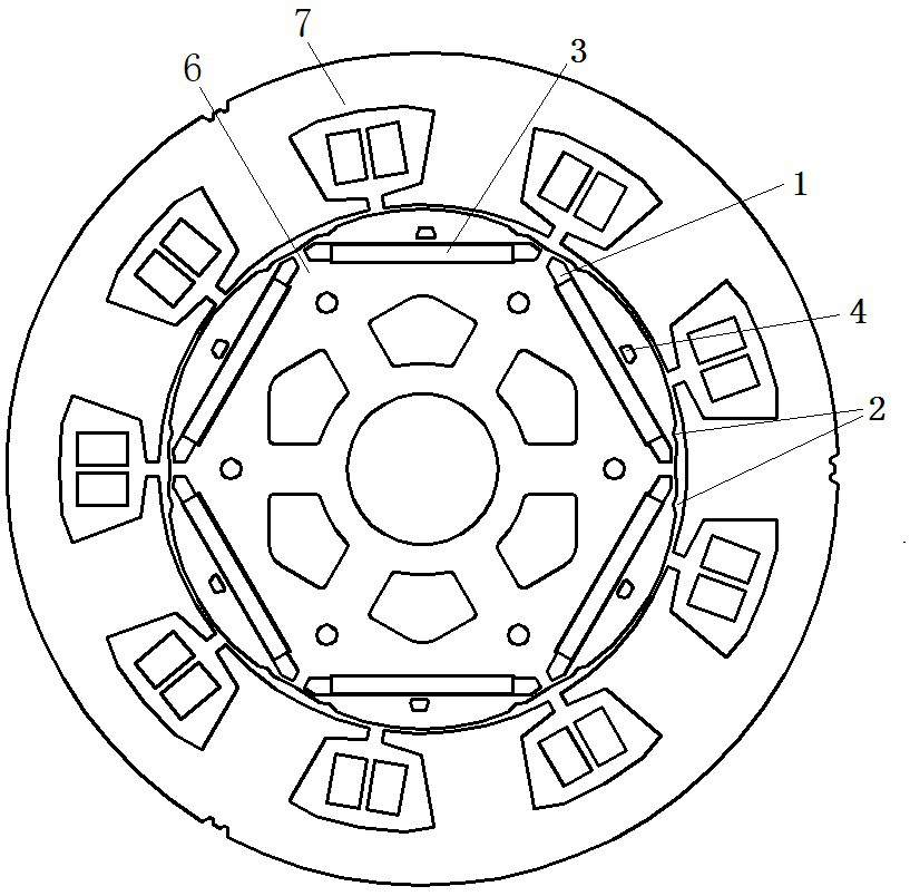
[0019] Such as Figure 1-2 As shown, a rotor for a rotating electric machine includes a rotor main body, six installation slots are evenly distributed around the radial outer side of the rotor main body, permanent magnets are arranged in the installation slots, and six radially outwardly convex arcs are arranged on the outer periphery of the rotor main body. surface and 12 grooves, the center of the arc surface is located on the radial inner side of the rotor body, the radius of the arc surface is smaller than the distance between the outer periphery of the rotor body and the center of the rotor body, and the rotor body is located on the outside of each pole permanent magnet. magnetic hole.

[0020] In order to achieve smaller rotor pole cutting, the radius of the arc surface is R1, the radial symmetry line of the arc surface passes...


PUM


Abstract

The invention discloses a rotary motor rotor and a motor, and relates to the field of motors. A rotor punching sheet of a traditional built-in permanent magnet rotary motor usually adopts the design that the outer circle of a rotor is a whole circle, and the problems that the air gap flux density harmonic content is large, the tooth groove positioning torque is large, the load torque fluctuation is large, and then motor noise and vibration are large are caused. Mounting grooves are formed in the radial outer side of a rotor body in a surrounding mode, permanent magnets are arranged in the mounting grooves, a plurality of outwards-protruding arc faces and a plurality of grooves are formed in the periphery of the rotor body, the radius of each arc face is smaller than the distance between the far end of the periphery of the rotor body and the center of the rotor body, and magnetic isolation holes are formed in the outer side of each permanent magnet on the rotor body. The periphery of the rotor main body is changed into eccentric cambered surface pole cutting and groove forming, so that the rotor air-gap magnetism can be adjusted, the sinusoidal property of a motor air-gap magnetic field is effectively improved, the cogging positioning moment of a motor is properly weakened, the motor performance is improved, and the noise and vibration of the motor are reduced.

Description

technical field [0001] The invention relates to the field of motors, in particular to a rotor of a rotating electrical machine and a motor. Background technique [0002] At present, the traditional built-in permanent magnet rotating motor rotor punching usually adopts the design of the outer circle of the rotor as a full circle or the design of an eccentric circle for simply cutting the poles of the rotor. When the rotor is designed as a full circle, the air gap of the motor is uniform, although The overall average air-gap magnetic density is high, but the problem is that the air-gap magnetic density has a large harmonic content, the cogging positioning torque is large, and the load torque fluctuates greatly, which leads to large motor noise and vibration; simple rotor pole cutting When the eccentric circle is designed, although the air-gap flux density waveform is relatively sinusoidal, the flux density harmonics and cogging torque are greatly reduced, but the large-scale p...

Claims


Application Information

Patent Timeline
Patent Type & Authority Applications(China)
IPC IPC(8): H02K1/27H02K21/02
CPCH02K1/276H02K21/025H02K2201/03H02K2213/03
Inventor 黎楚波胡吉亮严伟灿齐文艺魏瑜桑
Owner WOLONG ELECTRIC GRP CO LTD
Why Eureka
Try Eureka