
Intelligent manufacturing optical fiber punching die hole capable of automatic cooling based on pressure

An automatic cooling and intelligent manufacturing technology, applied in the field of mobile communication, can solve the problems of shortening the life of the punching hole, leaving a lot of copper slag, affecting the optical fiber polishing, etc., and improving the work efficiency.

Inactive Publication Date: 2021-04-09
南京南唐信息技术有限公司
View PDF0 Cites 0 Cited by
  • Summary
  • Abstract
  • Description
  • Claims
  • Application Information

AI Technical Summary

Problems solved by technology

[0002] With the continuous development of science and technology, mobile communication technology is also improving day by day. Mobile communication technology is a new development of communication technology. It is an emerging technology that uses mobile terminal equipment to communicate, realize information exchange, and share resources. The network cable is one of the products of mobile communication technology. The manufacture of the network cable is quite cumbersome and requires many steps. At the beginning, it needs to be polished with copper wire to meet the specifications of the network cable. However, when the die hole is polished, the temperature on the surface of the equipment It will rise, and the long-term high temperature environment will shorten the life of the die hole, and a lot of copper slag will remain on the surface of the die hole, which will affect the polishing of the optical fiber

Method used


Image

  • Intelligent manufacturing optical fiber punching die hole capable of automatic cooling based on pressure
  • Intelligent manufacturing optical fiber punching die hole capable of automatic cooling based on pressure
  • Intelligent manufacturing optical fiber punching die hole capable of automatic cooling based on pressure

Examples


Embodiment Construction

[0020] The following will clearly and completely describe the technical solutions in the embodiments of the present invention with reference to the accompanying drawings in the embodiments of the present invention. Obviously, the described embodiments are only some, not all, embodiments of the present invention. Based on the embodiments of the present invention, all other embodiments obtained by persons of ordinary skill in the art without making creative efforts belong to the protection scope of the present invention.

[0021] The implementation of the intelligent manufacturing of optical fiber punching holes based on pressure automatic cooling is as follows:

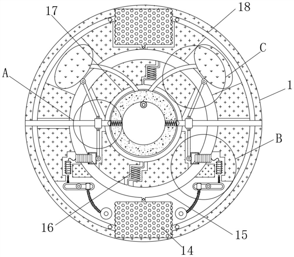
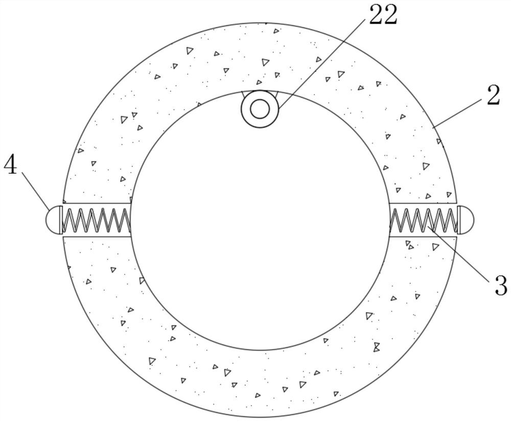
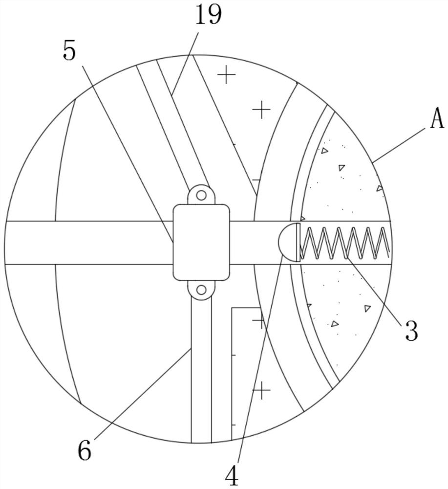
[0022] see Figure 1-5 , an optical fiber die hole for intelligent manufacturing based on pressure automatic cooling, including a housing 1, a material hole 2 is fixedly installed inside the housing 1, springs 3 are fixedly connected to both sides of the material hole 2, and the material hole 2 is inside the housing 1 ...


PUM


Abstract

The invention provides an intelligent manufacturing optical fiber punching die hole capable of automatic cooling based on pressure, and relates to the technical field of mobile communication. The intelligent manufacturing optical fiber punching die hole capable of automatic cooling based on pressure comprises a shell, wherein a material hole is fixedly formed in the shell, springs are fixedly connected to the two sides of the material hole, sliding blocks are slidably connected to the interior of the shell, and pushing rods are fixedly connected to the bottoms of the sliding blocks. Copper wires extrude the material hole to enable the springs to drive U-shaped covers to move, the resistance of rheostats is changed through cooperative use of the sliding blocks and the pushing rods, through cooperative use of electromagnets and magnetic pole columns, guide rods extrude water bags to enable water in the water bags to enter a cooling ring and then return to the water bags through a return pipe, so that the automatic cooling effect is realized, and through cooperative use of the sliding blocks and a moving rod, gas sprayed out of a gas spraying valve is used for cleaning copper slag, and the effect of improving the working efficiency is achieved.

Description

technical field [0001] The invention relates to the technical field of mobile communication, in particular to an optical fiber punching hole for intelligent manufacturing based on pressure automatic cooling. Background technique [0002] With the continuous development of science and technology, mobile communication technology is also improving day by day. Mobile communication technology is a new development of communication technology. It is an emerging technology that uses mobile terminal equipment to communicate, realize information exchange, and share resources. The network cable is one of the products of mobile communication technology. The manufacture of the network cable is quite cumbersome and requires many steps. At the beginning, it needs to be polished with copper wire to meet the specifications of the network cable. However, when the die hole is polished, the temperature on the surface of the equipment The high temperature environment for a long time will shorten...

Claims


Application Information

Patent Timeline
IPC IPC(8): B08B5/02F25D17/02
CPCB08B5/02F25D17/02
Inventor 裴博
Owner 南京南唐信息技术有限公司
Learn More