
Wood rod forming equipment for wood processing

A technology for forming equipment and wooden sticks, which is applied to wood processing equipment, manufacturing of wooden sticks, forming/shaping machines, etc., can solve the problems of hard texture and ring cutter stuck in the wood, etc., and achieve the effect of saving manpower

Pending Publication Date: 2021-04-09
蔡宦翼
View PDF6 Cites 2 Cited by
  • Summary
  • Abstract
  • Description
  • Claims
  • Application Information

AI Technical Summary

Problems solved by technology

[0004] In order to overcome the disadvantages that the texture of wood is usually hard, it is difficult to cut wood directly into wooden sticks smoothly, and it is easy to make the circular cutter stuck in the wood. , mechanized stick forming equipment for wood processing that cuts wood into sticks

Method used


Image

  • Wood rod forming equipment for wood processing
  • Wood rod forming equipment for wood processing
  • Wood rod forming equipment for wood processing

Examples


Embodiment 1

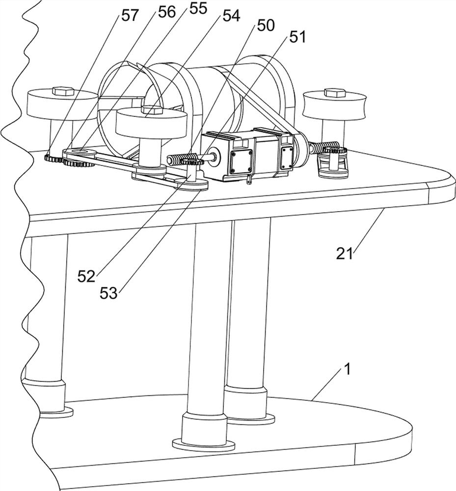
[0061] A wood rod forming equipment for wood processing, such as figure 1 As shown, it includes a bottom plate 1, a support mechanism 2 and a circle cutting mechanism 3. The top of the bottom plate 1 is provided with a support mechanism 2, and the support mechanism 2 is provided with a circle cutting mechanism 3.

[0062] Such as figure 2 As shown, the support mechanism 2 includes a support column 20 and an installation platform 21 , three support columns 20 are provided on the left and right sides of the top of the bottom plate 1 , and the installation platform 21 is connected between the tops of the support columns 20 .

[0063] Such as figure 2As shown, the circle cutting mechanism 3 includes a mounting plate 30, a motor 31, a rotating cylinder 32, the first pulley group 33 and a rotary cutter 34, and the left and right sides of the top of the mounting table 21 are symmetrically provided with the mounting plate 30, and the right side of the mounting table 21 top right A...

Embodiment 2

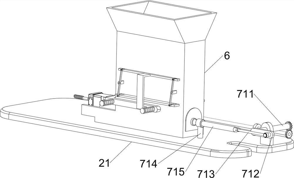
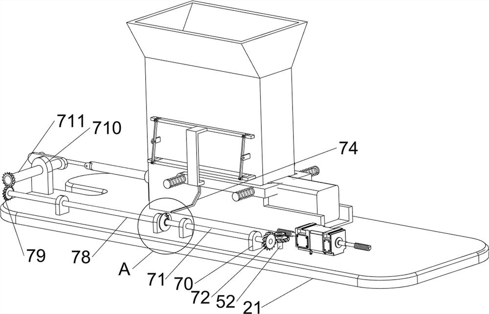
[0066] On the basis of Example 1, such as figure 2 As shown, a discharge mechanism 4 is also included, and the discharge mechanism 4 includes a first rotating shaft 40, a first worm 41, a first turbine 42, a second pulley set 43, a discharge wheel 44, a second rotating shaft 45, a third The belt pulley set 46 and the first gear set 47, the top right side of the mounting table 21 is provided with a first rotating shaft 40, the upper side of the first rotating shaft 40 is provided with a first turbine 42, and the output shaft on the right side of the motor 31 is provided with a first worm 41 , the first worm 41 is meshed with the first worm gear 42, the front and rear symmetrical rotation of the top right side of the installation platform 21 is provided with a discharge wheel 44, the rotation of the right rear side of the top of the installation platform 21 is provided with a second rotating shaft 45, and the front side discharge wheel 44 and the first rotating shaft 40 are con...


PUM


Abstract

The invention relates to wood rod forming equipment, in particular to wood rod forming equipment for wood processing. According to the wood rod forming equipment for wood processing, a cutter does not need to be manually used for cutting wood, and the wood is mechanically cut into wood rods. According to the technical scheme, the wood rod forming equipment for wood processing comprises a bottom plate and a circle cutting mechanism, and a supporting mechanism is arranged at the top of the bottom plate; and the circle cutting mechanism is arranged on the supporting mechanism. Through cooperation of the supporting mechanism and the circle cutting mechanism, after a worker puts wood well, a motor is started to work, and meanwhile, the wood is pushed to move rightwards to be cut into the wood rod; and through the cooperation of a discharging mechanism and a feeding mechanism, after the worker puts the wood rods well, the wood can be moved to be cut without manual pushing, and the worker only needs to continuously put the wood to be cut well.

Description

technical field [0001] The present invention relates to a kind of wood stick forming equipment, in particular to a kind of wood stick forming equipment for wood processing. Background technique [0002] In the actual use of wood, wooden sticks are often used. Wooden sticks can be used as legs between stools, handles of shovels and handles of mops, etc. Therefore, it is necessary to cut the wood to make it into a wooden stick. The cutting work is done manually. After the wood is put in place, the wood can be cut into sticks with a circular cutter. However, the texture of the wood is usually hard, and it is difficult to cut the wood directly into wooden sticks smoothly. Stick, easy to get the ring cutter stuck in the wood. [0003] Therefore need to design a kind of needn't manually use cutter to cut wood, mechanized wood is cut into wood stick molding equipment for wood processing. Contents of the invention [0004] In order to overcome the disadvantages that the texture ...

Claims


Application Information

Patent Timeline
Patent Type & Authority Applications(China)
IPC IPC(8): B27L9/00B27C5/02B27C5/06B27C5/08
CPCB27C5/02B27C5/06B27C5/08B27L9/00
Inventor 蔡宦翼
Owner 蔡宦翼
Learn More