Hovercar

A flying car and body technology, applied in the field of flying cars, can solve problems that hinder the development and progress of the aerial vehicle industry

Pending Publication Date: 2021-04-09
朱上翔
View PDF16 Cites 2 Cited by
  • Summary
  • Abstract
  • Description
  • Claims
  • Application Information

AI Technical Summary

Problems solved by technology

But in the long run, this tendency will hinder the f...

Method used


Image

  • Hovercar
  • Hovercar
  • Hovercar

Examples


Embodiment

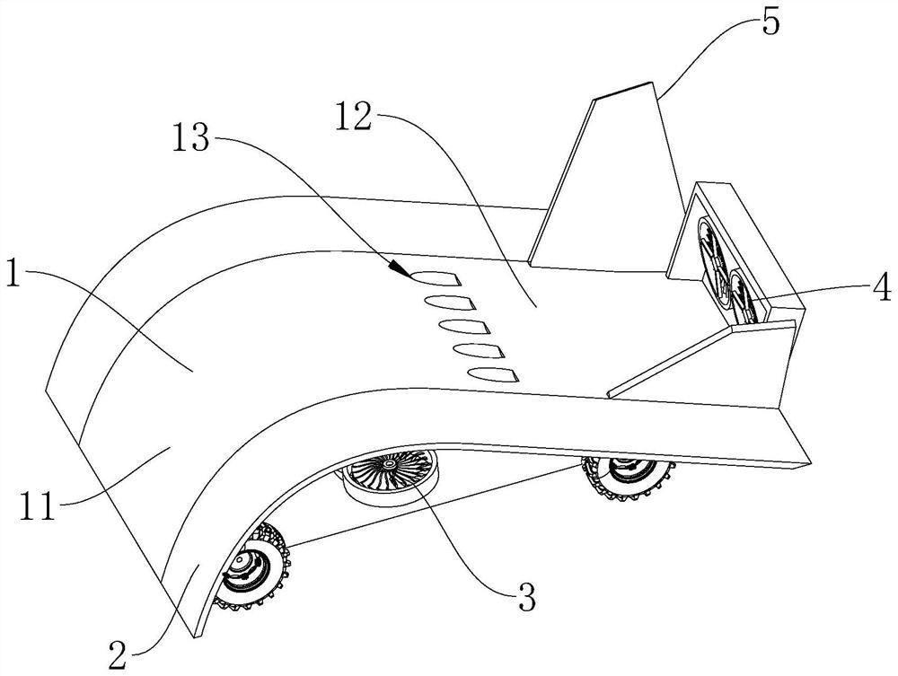
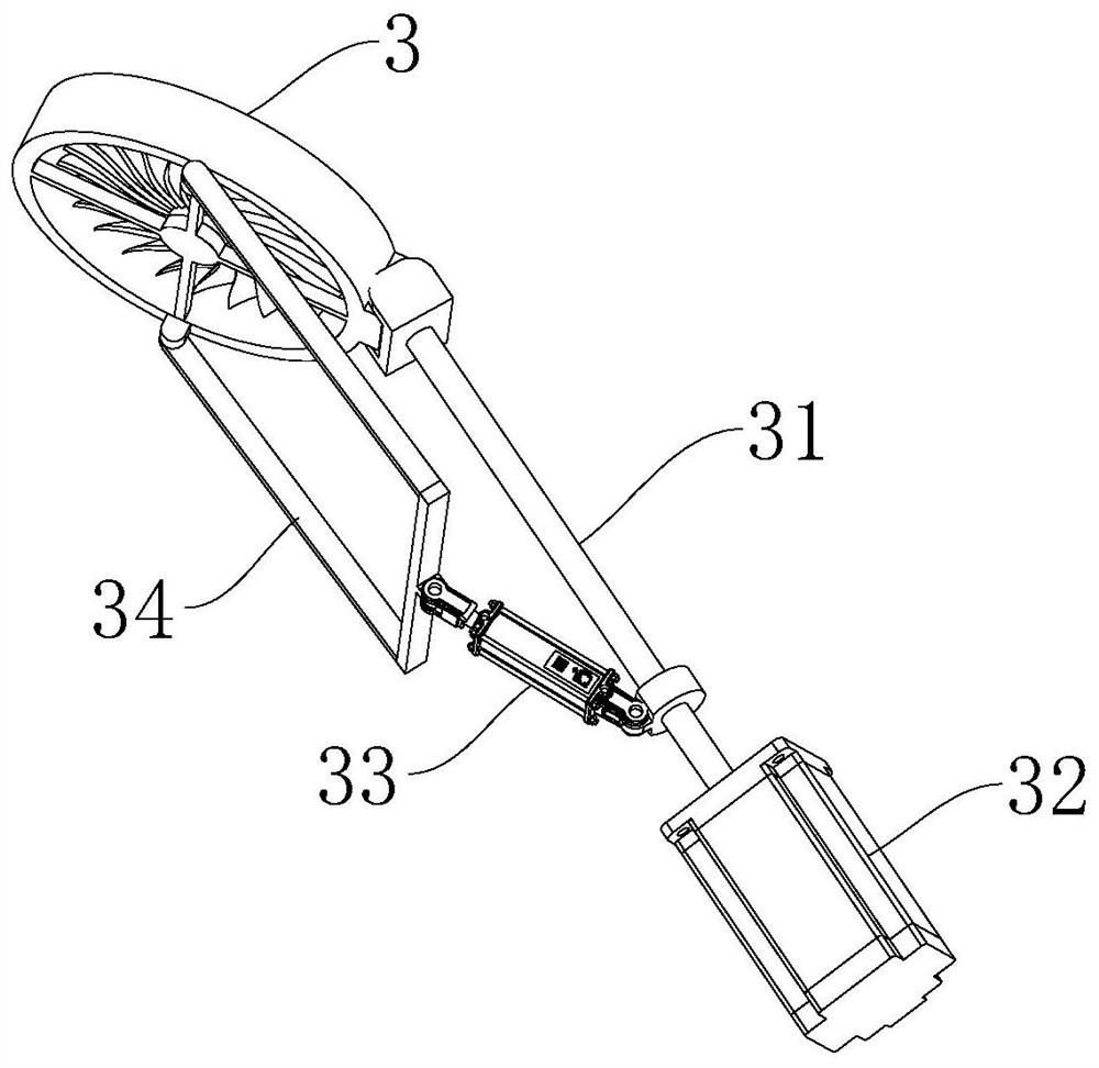
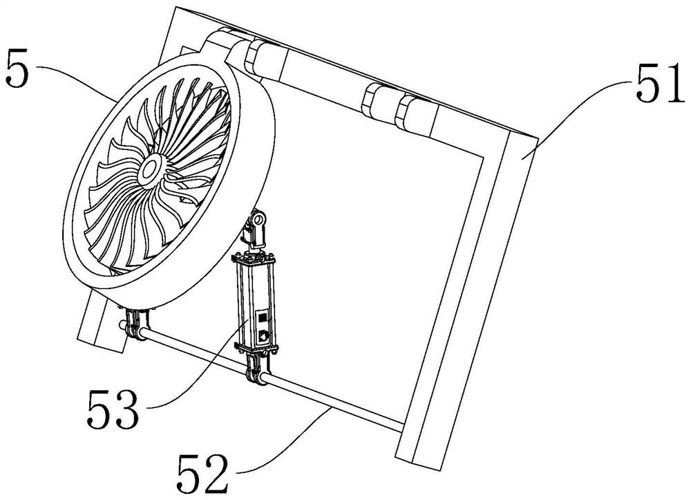
[0037] Such as figure 1 As shown, a flying car is provided for this embodiment, which includes an airfoil body 1, a retractable wing-end vortex increasing device 2, a foldable empennage 5, a first ducted fan engine 3 and a second ducted fan engine 4. The retractable wing end vortex increasing device 2 is arranged on the side wall of the airfoil body 1, the foldable empennage 5 is installed on the upper surface of the airfoil body 1, and a plurality of first ducted fan engines 3 are evenly arranged on the airfoil body 1 On both sides of the airfoil body, the second ducted fan engine 4 is arranged at the tail of the airfoil body 1 .

[0038] In some embodiments of the present invention, the flying car of the present design is a ground-air amphibious aircraft with a wing body (or wingless). Its body is similar to a common car, the bottom of the wing-shaped body 1 is provided with the same tires as the car, and the foldable tail 5 is installed at the rear. And the tail is also i...


PUM


Abstract

The invention provides a hovercar, and relates to the technical field of hovercars. The hovercar comprises an aerofoil vehicle body, a telescopic wing end standing vortex high lift device, a foldable empennage, a plurality of first ducted fan engines and a plurality of second ducted fan engines; the telescopic wing end standing vortex high lift device is arranged on the side wall of the aerofoil vehicle body, and the foldable empennage is arranged on the upper surface of the aerofoil vehicle body; the plurality of first ducted fan engines are evenly arranged on the two sides of the aerofoil vehicle body, and the second ducted fan engines are arranged at the tail of the aerofoil vehicle body. A novel appearance conforming to aerodynamics and flight dynamics principles is adopted, so that the lift force of the hovercar is improved.

Description

technical field [0001] The present invention relates to the technical field of flying cars, in particular to a flying car. Background technique [0002] Car travel has become an indispensable way of travel in modern life, but with the increase of vehicles, traffic jams have also become a major problem, thus seeking a three-dimensional traffic solution, resulting in the concept of flying cars. So far, nearly 200 flying car companies around the world have developed dozens of flying cars. In fact, many products are not ideal flying cars, most of them are just vertical take-off and landing flying machines. The ideal flying car is; it is a car with good driving performance on land; when needed, it can be lifted from any position in front of the traffic lane in use when it is needed; A light aircraft with good flight performance. However, so far there is no so-called flying car that has reached the real flying car. The fundamental reason is that in order to develop an ideal fl...

Claims


Application Information

Patent Timeline
IPC IPC(8): B60F5/02B64C11/00B62D35/00
CPCB60F5/02B64C11/00B62D35/00Y02T10/82
Inventor 朱上翔李嵩
Owner 朱上翔
Why Eureka
Try Eureka